annual report annual report annual report annual report 2005
annual report annual report annual report annual report 2005
annual report annual report annual report annual report 2005

You also want an ePaper? Increase the reach of your titles
YUMPU automatically turns print PDFs into web optimized ePapers that Google loves.
142<br />
NUCLEONIC CONTROL SYSTEMS AND ACCELERATORS<br />
signal from the pulse radiolysis experimental set.<br />
The signal is transfer by the optical fiber “FO” and<br />
Adam-4060 couple module (Fig.2).<br />
Figure 3 shows the pulse leading edges in selected<br />
places (see Fig.2) of the new trigger circuits.<br />
The pulse leading edges was recorded by a digital<br />
Tektronix oscilloscope, TDS620 type, and the oscillograms<br />
were taken by QV-100 Casio digital<br />
camera and computer processed. We can state that<br />
the pulses on the output of the HFBR-2528 “receiver”<br />
(Fig. 3a) can be obtained with rise time less<br />
than 5 ns. It was a significant achievement because<br />
own rise time of the HFBR-2528 receiver is 12 ns<br />
typically. Radiolysis oscilloscopes can be, therefore<br />
triggered with jitter below 1 ns. Trigger circuit of<br />
the nanosecond modulator is more complicated.<br />
Additional electronic subassemblies and elements<br />
are inserted between the output of the HFBR-2528<br />
“receiver” and the input HTS 80-12-UF high voltage<br />
transistor switch of the nanosecond modulator.<br />
The amplifier built-up, inter alia, from the<br />
EL2244 integrated circuit and IR4427 driver are<br />
the subassemblies. Resistor (1 kΩ), capacitor (4.7<br />
nF – relatively big capacity in this case) and<br />
1.5KE7.7A diode to overvoltage protection are the<br />
elements set up in parallel to the switch input. It<br />
was necessary to reduce – to value less than noise-<br />
-margin – the amplitude of the disturbing pulse<br />
on the input of the HTS 80-12-UF switch. Anode<br />
modulator (60 kV/200 ns) of the accelerator gun<br />
[6] is the source of the disturbing pulse. So, therefore<br />
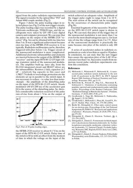
considerable reduction occurred of the pulse<br />
rate-of-rise from about 1 V/ns on the output of<br />
Fig.4. Part of 30 pulse leading edges.<br />
the HFBR-2528 receiver to about 0.1 V/ns on the<br />
input of the HTS 80-12-UF switch. Delay time of<br />
the switch is 60 ns with an effect from the moment<br />
of time in which the voltage on the input of the<br />
switch achieved an adequate value. Amplitude of<br />
the trigger pulse ought to range from 2 to 10 V.<br />
The start action of the switch can be recognized<br />
by the occurrence of characteristic pulse ripple<br />
(Fig.3b).<br />
Essential fragments of the successive 30 pulses<br />
on the HTS 80-12-UF switch input is shown in<br />
Fig.4. We can state that jitter of the trigger line of<br />
the nanosecond modulator is not more than 2 ns<br />
even for the most disadvantageous case i.e. for least<br />
rate-of-rise the voltage range from 2 to 3 V. Jitter<br />
of the nanosecond modulator is practically the<br />
same because own jitter of the switch is only 100<br />
ps.<br />
A series of accelerator pulses in radiolysis experiments<br />
as a rule is less than or equal to 10 pulses.<br />
In conclusion, we can state that the new trigger<br />
lines assure the operation jitter of the LAE 10 accelerator<br />
less than 5 ns. Successive results from numerous<br />
recent pulse radiolysis experiments confirm<br />
this conclusion.<br />
References<br />
[1]. Mirkowski J., Wiśniowski P., Bobrowski K.: A nanosecond<br />
pulse radiolysis system dedicated to the new<br />
LAE 10 accelerator in the INCT. In: INCT Annual<br />
Report 2000. Institute of Nuclear Chemistry and Technology,<br />
Warszawa 2001, pp.31-33.<br />
[2]. Bobrowski K., Potocki D., Hug G.L., Marciniak B.,<br />
Schöneich C.: Oxidation of methionine-containing<br />
peptides: spectral and conductometric pulse radiolysis<br />
studies. Proccedings of the Radam Conference <strong>2005</strong><br />
“Radiation Damage in Bimolecular Systems”, Potsdam,<br />
Germany, 17-20.03.<strong>2005</strong>, P-08, p.55.<br />
[3]. Grodkowski J., Nygo M., Mirkowski J.: Nukleonika,<br />
50, Suppl.2, 35-38 (<strong>2005</strong>).<br />
[4]. Grodkowski J., Mirkowski J., Płusa M., Getoff N., Popov<br />
P.: Radiat. Phys. Chem., 69, 379-386 (2004).<br />
[5]. Bielik M., Dźwigalski Z.: Fiber-optic control system<br />
for an electron gun. Proceedings of the 2nd National<br />
Symposium PLASMA’95 “Research and applications<br />
of plasmas”, Warszawa, Poland, 26-28.06.1995, Vol.1,<br />
pp.279-282.<br />
[6]. Dźwigalski Z., Zimek Z.: Electron. Technol., 30, 4,<br />
331-334 (1997).<br />
[7]. Dźwigalski Z., Zimek Z.: Formowanie krótkich impulsów<br />
w akceleratorze liniowym elektronów. In: Technika<br />
jądrowa w przemyśle, medycynie, rolnictwie i ochronie<br />
środowiska. T.2. Instytut Chemii i Techniki Jądrowej,<br />
Warszawa 2002. Raporty IChTJ. Seria A nr 2/2002,<br />
p.557 (in Polish).<br />
[8]. Dźwigalski Z., Zimek Z.: Zeszyty Naukowe Politechniki<br />
Warszawskiej, seria Elektronika, 123, 215-218 (1999),<br />
in Polish.