

3.22EjemploDRM007 Co..
3.22EjemploDRM007 Co..
3.22EjemploDRM007 Co..

Create successful ePaper yourself
Turn your PDF publications into a flip-book with our unique Google optimized e-Paper software.
Introduction and Setup<br />
OR<br />
PRESCALER<br />
UP/DOWN<br />
COUNTER<br />
PRESCALER<br />
÷ 1, 2, 3, OR 8 ÷ 1, 2, 3, OR 8<br />
PWM RELOAD AND INTERRUPT<br />
INTERRUPTS<br />
PWM<br />
GENERATORS<br />
COMPARATORS<br />
DOUBLE<br />
BUFFERED<br />
REGISTERS<br />
CONTROL<br />
PWM<br />
MODE SELECT<br />
DEADTIME<br />
INSERTION<br />
DIRECT<br />
OUTPUT CONTROL<br />
DISTORTION<br />
CORRECTION<br />
FAULT<br />
PROTECTION<br />
FAULT<br />
PARTITIONING<br />
FAULT<br />
MODE SELECT<br />
OUTPUT<br />
POLARITY<br />
CONTROL<br />
HIGH CURRENT<br />
DRIVERS<br />
PWM1<br />
PWM2<br />
PWM3<br />
PWM4<br />
PWM5<br />
PWM6<br />
MOTOR CURRENT POLARITIES<br />
SYSTEM FAULTS<br />
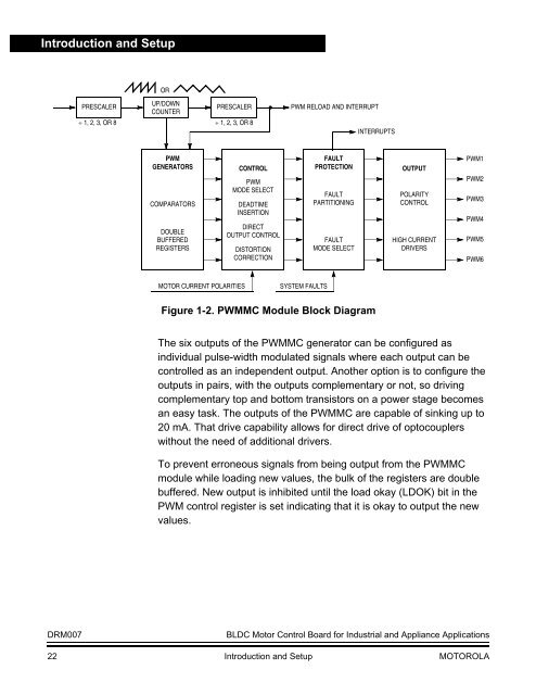
Figure 1-2. PWMMC Module Block Diagram<br />
The six outputs of the PWMMC generator can be configured as<br />
individual pulse-width modulated signals where each output can be<br />
controlled as an independent output. Another option is to configure the<br />
outputs in pairs, with the outputs complementary or not, so driving<br />
complementary top and bottom transistors on a power stage becomes<br />
an easy task. The outputs of the PWMMC are capable of sinking up to<br />
20 mA. That drive capability allows for direct drive of optocouplers<br />
without the need of additional drivers.<br />
To prevent erroneous signals from being output from the PWMMC<br />
module while loading new values, the bulk of the registers are double<br />
buffered. New output is inhibited until the load okay (LDOK) bit in the<br />
PWM control register is set indicating that it is okay to output the new<br />
values.<br />
DRM007<br />
BLDC Motor <strong>Co</strong>ntrol Board for Industrial and Appliance Applications<br />
22 Introduction and Setup MOTOROLA


