

3.22EjemploDRM007 Co..
3.22EjemploDRM007 Co..
3.22EjemploDRM007 Co..

You also want an ePaper? Increase the reach of your titles
YUMPU automatically turns print PDFs into web optimized ePapers that Google loves.
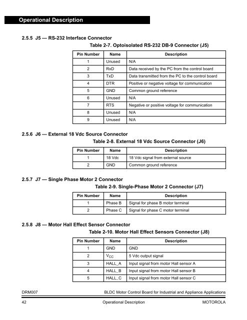
Operational Description<br />
2.5.5 J5 — RS-232 Interface <strong>Co</strong>nnector<br />
Table 2-7. Optoisolated RS-232 DB-9 <strong>Co</strong>nnector (J5)<br />
Pin Number Name Description<br />
1 Unused N/A<br />
2 RxD Data received by the PC from the control board<br />
3 TxD Data transmitted from the PC to the control board<br />
4 DTR Positive or negative voltage for communication<br />
5 GND <strong>Co</strong>mmon ground reference<br />
6 Unused N/A<br />
7 RTS Negative or positive voltage for communication<br />
8 Unused N/A<br />
9 Unused N/A<br />
2.5.6 J6 — External 18 Vdc Source <strong>Co</strong>nnector<br />
Table 2-8. External 18 Vdc Source <strong>Co</strong>nnector (J6)<br />
Pin Number Name Description<br />
1 18 Vdc 18 Vdc signal from external source<br />
2 GND <strong>Co</strong>mmon ground reference<br />
2.5.7 J7 — Single Phase Motor 2 <strong>Co</strong>nnector<br />
Table 2-9. Single-Phase Motor 2 <strong>Co</strong>nnector (J7)<br />
Pin Number Name Description<br />
1 Phase B Signal for phase B motor terminal<br />
2 Phase C Signal for phase C motor terminal<br />
2.5.8 J8 — Motor Hall Effect Sensor <strong>Co</strong>nnector<br />
Table 2-10. Motor Hall Effect Sensors <strong>Co</strong>nnector (J8)<br />
Pin Number Name Description<br />
1 GND GND<br />
2 V CC 5 Vdc output signal<br />
3 HALL_A Input signal from motor Hall sensor A<br />
4 HALL_B Input signal from motor Hall sensor B<br />
5 HALL_C Input signal from motor Hall sensor C<br />
DRM007<br />
BLDC Motor <strong>Co</strong>ntrol Board for Industrial and Appliance Applications<br />
42 Operational Description MOTOROLA


