

3.22EjemploDRM007 Co..
3.22EjemploDRM007 Co..
3.22EjemploDRM007 Co..

Create successful ePaper yourself
Turn your PDF publications into a flip-book with our unique Google optimized e-Paper software.
Hardware Design <strong>Co</strong>nsiderations<br />
3-Phase H-Bridge<br />
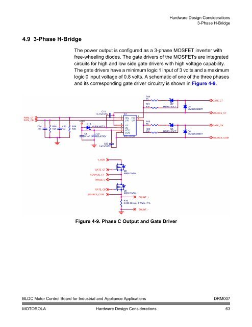
4.9 3-Phase H-Bridge<br />
The power output is configured as a 3-phase MOSFET inverter with<br />
free-wheeling diodes. The gate drivers of the MOSFETs are integrated<br />
circuits for high and low side gate drivers with high voltage capability.<br />
The gate drivers have a minimum logic 1 input of 3 volts and a maximum<br />
logic 0 input voltage of 0.8 volts. A schematic of one of the three phases<br />
and its corresponding gate driver circuitry is shown in Figure 4-9.<br />
PWM_CT<br />
PWM_CB<br />
C54<br />
1nF<br />
R58<br />
10K<br />
C53<br />
1nF<br />
R59<br />
10K<br />
+15V<br />
C8<br />
0.1uF<br />
C10<br />
0.47uF/25V<br />
D19<br />
MURA160T3<br />
+ C9<br />
33uF/50V<br />
2<br />
3<br />
6<br />
8<br />
1<br />
4<br />
IC1<br />
HIN<br />
LIN<br />
HO 7<br />
LO 5<br />
VS<br />
VB<br />
VCC<br />
COM<br />
IR2101/SO<br />
R44<br />
75<br />
R21<br />
600<br />
R45<br />
75<br />
R20<br />
600<br />
D7<br />
MBRS130CT<br />
D5<br />
MBRS130CT<br />
D8<br />
MMSZ5248BT1<br />
D6<br />
MMSZ5248BT1<br />
GATE_CT<br />
SOURCE_CT<br />
GATE_CB<br />
SOURCE_COM<br />
C30<br />
0.47uF/25V<br />
V_BUS<br />
GATE_CT<br />
SOURCE_CT<br />
Q5<br />
IRFB17N50L<br />
PHASE_C<br />
GATE_CB<br />
SOURCE_COM<br />
Q6<br />
IRFB17N50L<br />
SHUNT_+<br />
R19<br />
0.005 Ohms / 3 Watts / 1%<br />
SHUNT_-<br />
Figure 4-9. Phase C Output and Gate Driver<br />
BLDC Motor <strong>Co</strong>ntrol Board for Industrial and Appliance Applications<br />
DRM007<br />
MOTOROLA Hardware Design <strong>Co</strong>nsiderations 63


