

3.22EjemploDRM007 Co..
3.22EjemploDRM007 Co..
3.22EjemploDRM007 Co..

Create successful ePaper yourself
Turn your PDF publications into a flip-book with our unique Google optimized e-Paper software.
Introduction and Setup<br />
System <strong>Co</strong>ncept<br />
120 / 230 VAC<br />
3-PHASE<br />
INVERTER<br />
3-PHASE<br />
BLDC<br />
MOTOR<br />
SENSING CIRCUITRY<br />
FOR I, V, AND T<br />
USER INTERFACE<br />
FAULT<br />
ADC<br />
PWM<br />
RS-232<br />
16 x 2 LCD<br />
SCI I/O<br />
I/O<br />
SPEED PI<br />
CONTROLLER<br />
REQUIRED<br />
SPEED<br />
WASH PROCESS<br />
REQUIRED TABLE<br />
ACTUAL<br />
SPEED<br />
REQUIRED VOLTAGE<br />
1/T<br />
SIX-STEP VOLTAGE<br />
GENERATOR<br />
POSITION,<br />
DIRECTION<br />
RECOGNITION<br />
MC68HC908MR8<br />
CURRENT<br />
POSITION<br />
I/O<br />
HALL EFFECT<br />
SENSOR SIGNALS<br />
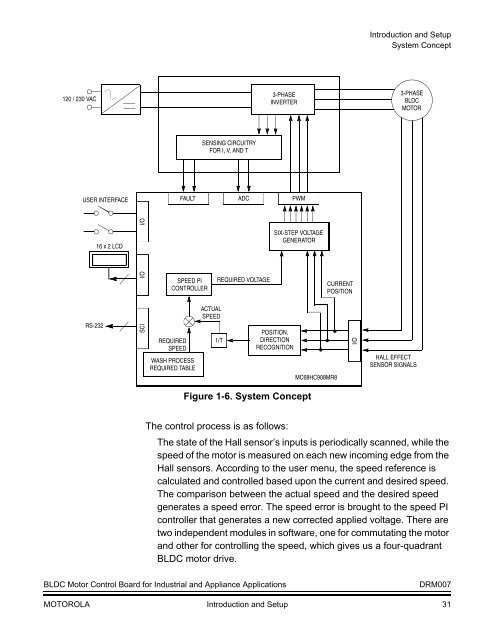
Figure 1-6. System <strong>Co</strong>ncept<br />
The control process is as follows:<br />
The state of the Hall sensor’s inputs is periodically scanned, while the<br />
speed of the motor is measured on each new incoming edge from the<br />
Hall sensors. According to the user menu, the speed reference is<br />
calculated and controlled based upon the current and desired speed.<br />
The comparison between the actual speed and the desired speed<br />
generates a speed error. The speed error is brought to the speed PI<br />
controller that generates a new corrected applied voltage. There are<br />
two independent modules in software, one for commutating the motor<br />
and other for controlling the speed, which gives us a four-quadrant<br />
BLDC motor drive.<br />
BLDC Motor <strong>Co</strong>ntrol Board for Industrial and Appliance Applications<br />
DRM007<br />
MOTOROLA Introduction and Setup 31


