

3.22EjemploDRM007 Co..
3.22EjemploDRM007 Co..
3.22EjemploDRM007 Co..

You also want an ePaper? Increase the reach of your titles
YUMPU automatically turns print PDFs into web optimized ePapers that Google loves.
Introduction and Setup<br />
Brief Overview to Brushless DC Motors<br />
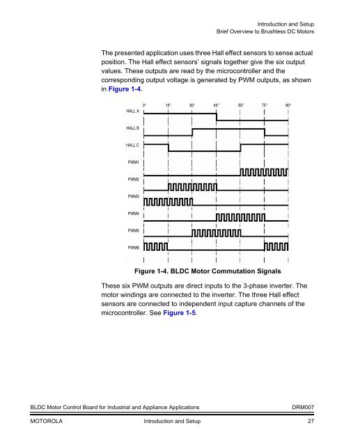
The presented application uses three Hall effect sensors to sense actual<br />
position. The Hall effect sensors’ signals together give the six output<br />
values. These outputs are read by the microcontroller and the<br />
corresponding output voltage is generated by PWM outputs, as shown<br />
in Figure 1-4.<br />
HALL A<br />
0° 15° 30° 45° 60° 75° 90°<br />
HALL B<br />
HALL C<br />
PWM1<br />
PWM2<br />
PWM3<br />
PWM4<br />
PWM5<br />
PWM6<br />
Figure 1-4. BLDC Motor <strong>Co</strong>mmutation Signals<br />
These six PWM outputs are direct inputs to the 3-phase inverter. The<br />
motor windings are connected to the inverter. The three Hall effect<br />
sensors are connected to independent input capture channels of the<br />
microcontroller. See Figure 1-5.<br />
BLDC Motor <strong>Co</strong>ntrol Board for Industrial and Appliance Applications<br />
DRM007<br />
MOTOROLA Introduction and Setup 27


