

3.22EjemploDRM007 Co..
3.22EjemploDRM007 Co..
3.22EjemploDRM007 Co..

You also want an ePaper? Increase the reach of your titles
YUMPU automatically turns print PDFs into web optimized ePapers that Google loves.
Hardware Design <strong>Co</strong>nsiderations<br />
Voltage Feedback<br />
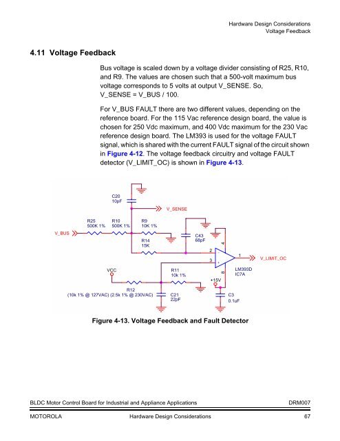
4.11 Voltage Feedback<br />
Bus voltage is scaled down by a voltage divider consisting of R25, R10,<br />
and R9. The values are chosen such that a 500-volt maximum bus<br />
voltage corresponds to 5 volts at output V_SENSE. So,<br />
V_SENSE = V_BUS / 100.<br />
For V_BUS FAULT there are two different values, depending on the<br />
reference board. For the 115 Vac reference design board, the value is<br />
chosen for 250 Vdc maximum, and 400 Vdc maximum for the 230 Vac<br />
reference design board. The LM393 is used for the voltage FAULT<br />
signal, which is shared with the current FAULT signal of the circuit shown<br />
in Figure 4-12. The voltage feedback circuitry and voltage FAULT<br />
detector (V_LIMIT_OC) is shown in Figure 4-13.<br />
C20<br />
10pF<br />
V_SENSE<br />
R25<br />
500K 1%<br />
R10<br />
500K 1%<br />
R9<br />
10K 1%<br />
V_BUS<br />
VCC<br />
R14<br />
15K<br />
R11<br />
10k 1%<br />
C43<br />
68pF<br />
2<br />
3<br />
+15V<br />
+<br />
-<br />
8 4<br />
1<br />
LM393D<br />
IC7A<br />
V_LIMIT_OC<br />
R12<br />
(10k 1% @ 127VAC) (2.5k 1% @ 230VAC)<br />
C21<br />
22pF<br />
C3<br />
0.1uF<br />
Figure 4-13. Voltage Feedback and Fault Detector<br />
BLDC Motor <strong>Co</strong>ntrol Board for Industrial and Appliance Applications<br />
DRM007<br />
MOTOROLA Hardware Design <strong>Co</strong>nsiderations 67


