

3.22EjemploDRM007 Co..
3.22EjemploDRM007 Co..
3.22EjemploDRM007 Co..

Create successful ePaper yourself
Turn your PDF publications into a flip-book with our unique Google optimized e-Paper software.
Hardware Design <strong>Co</strong>nsiderations<br />
4.12 Current and Voltage Limiter<br />
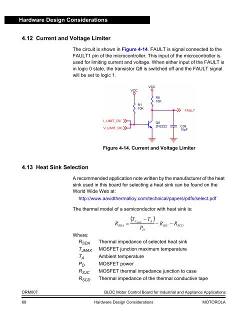
The circuit is shown in Figure 4-14. FAULT is signal connected to the<br />
FAULT1 pin of the microcontroller. This input of the microcontroller is<br />
used for limiting current and voltage. When either input of the FAULT is<br />
in logic 0 state, the transistor Q8 is switched off and the FAULT signal<br />
will be set to logic 1.<br />
VCC<br />
R1<br />
10K<br />
VCC<br />
R8<br />
10K<br />
FAULT<br />
I_LIMIT_OC<br />
V_LIMIT_OC<br />
Q8<br />
2N2222<br />
C38<br />
15pF<br />
Figure 4-14. Current and Voltage Limiter<br />
4.13 Heat Sink Selection<br />
A recommended application note written by the manufacturer of the heat<br />
sink used in this board for selecting a heat sink can be found on the<br />
World Wide Web at:<br />
http://www.aavidthermalloy.com/technical/papers/pdfs/select.pdf<br />
The thermal model of a semiconductor with heat sink is:<br />
Where:<br />
R SDA<br />
T JMAX<br />
T A<br />
P D<br />
R SJC<br />
R SCD<br />
R<br />
ϑDA<br />
=<br />
( T −T<br />
)<br />
J<br />
MAX<br />
P<br />
D<br />
A<br />
− R<br />
ϑJC<br />
− R<br />
ϑCD<br />
Thermal impedance of selected heat sink<br />
MOSFET junction maximum temperature<br />
Ambient temperature<br />
MOSFET power<br />
MOSFET thermal impedance junction to case<br />
Thermal impedance of the thermal conductive tape<br />
DRM007<br />
BLDC Motor <strong>Co</strong>ntrol Board for Industrial and Appliance Applications<br />
68 Hardware Design <strong>Co</strong>nsiderations MOTOROLA


