3.22EjemploDRM007 Co..
3.22EjemploDRM007 Co..
3.22EjemploDRM007 Co..
You also want an ePaper? Increase the reach of your titles
YUMPU automatically turns print PDFs into web optimized ePapers that Google loves.
Software Design <strong>Co</strong>nsiderations<br />
<strong>Co</strong>mmutation Algorithm<br />
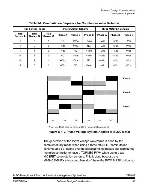
Table 5-2. <strong>Co</strong>mmutation Sequence for <strong>Co</strong>unterclockwise Rotation<br />
Hall Sensor Inputs Two MOSFET Scheme Three MOSFET Scheme<br />
Hall<br />
Sensor A<br />
Hall<br />
Sensor B<br />
Hall<br />
Sensor C<br />
Phase A Phase B Phase C Phase A Phase B Phase C<br />
1 0 1 NC +Vdc –Vdc –Vdc +Vdc –Vdc<br />
1 0 0 –Vdc +Vdc NC –Vdc +Vdc +Vdc<br />
1 1 0 –Vdc NC +Vdc –Vdc –Vdc +Vdc<br />
0 1 0 NC –Vdc +Vdc +Vdc –Vdc +Vdc<br />
0 1 1 +Vdc –Vdc NC +Vdc –Vdc –Vdc<br />
0 0 1 +Vdc NC –Vdc +Vdc +Vdc –Vdc<br />
Phase A<br />
Phase B<br />
Phase C<br />
0° 60° 120° 180° 240° 300°<br />
Note: Use black area for three MOSFET commutation scheme.<br />
Figure 5-4. 3-Phase Voltage System Applies to BLDC Motor<br />
The generation of the PWM voltage waveforms is done by the<br />
complementary mode when using a three MOSFET commutation<br />
scheme, and by loading 0 to the corresponding phases and configuring<br />
the microcontroller to have a TOPNEG PWM when using a two<br />
MOSFET commutation scheme. This is done because the<br />
M68HC908MRx microcontrollers don’t have the PWM MASK option, so<br />
BLDC Motor <strong>Co</strong>ntrol Board for Industrial and Appliance Applications<br />
DRM007<br />
MOTOROLA Software Design <strong>Co</strong>nsiderations 81


