3.22EjemploDRM007 Co..
3.22EjemploDRM007 Co..
3.22EjemploDRM007 Co..
Create successful ePaper yourself
Turn your PDF publications into a flip-book with our unique Google optimized e-Paper software.
Hardware Design <strong>Co</strong>nsiderations<br />
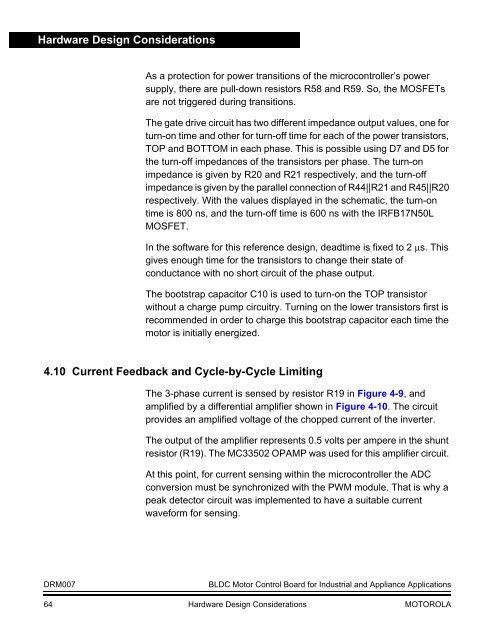
As a protection for power transitions of the microcontroller’s power<br />
supply, there are pull-down resistors R58 and R59. So, the MOSFETs<br />
are not triggered during transitions.<br />
The gate drive circuit has two different impedance output values, one for<br />
turn-on time and other for turn-off time for each of the power transistors,<br />
TOP and BOTTOM in each phase. This is possible using D7 and D5 for<br />
the turn-off impedances of the transistors per phase. The turn-on<br />
impedance is given by R20 and R21 respectively, and the turn-off<br />
impedance is given by the parallel connection of R44||R21 and R45||R20<br />
respectively. With the values displayed in the schematic, the turn-on<br />
time is 800 ns, and the turn-off time is 600 ns with the IRFB17N50L<br />
MOSFET.<br />
In the software for this reference design, deadtime is fixed to 2 µs. This<br />
gives enough time for the transistors to change their state of<br />
conductance with no short circuit of the phase output.<br />
The bootstrap capacitor C10 is used to turn-on the TOP transistor<br />
without a charge pump circuitry. Turning on the lower transistors first is<br />
recommended in order to charge this bootstrap capacitor each time the<br />
motor is initially energized.<br />
4.10 Current Feedback and Cycle-by-Cycle Limiting<br />
The 3-phase current is sensed by resistor R19 in Figure 4-9, and<br />
amplified by a differential amplifier shown in Figure 4-10. The circuit<br />
provides an amplified voltage of the chopped current of the inverter.<br />
The output of the amplifier represents 0.5 volts per ampere in the shunt<br />
resistor (R19). The MC33502 OPAMP was used for this amplifier circuit.<br />
At this point, for current sensing within the microcontroller the ADC<br />
conversion must be synchronized with the PWM module. That is why a<br />
peak detector circuit was implemented to have a suitable current<br />
waveform for sensing.<br />
DRM007<br />
BLDC Motor <strong>Co</strong>ntrol Board for Industrial and Appliance Applications<br />
64 Hardware Design <strong>Co</strong>nsiderations MOTOROLA


