

3.22EjemploDRM007 Co..
3.22EjemploDRM007 Co..
3.22EjemploDRM007 Co..

Create successful ePaper yourself
Turn your PDF publications into a flip-book with our unique Google optimized e-Paper software.
Hardware Design <strong>Co</strong>nsiderations<br />
This peak is stored in capacitor C37 when current flows through R19.<br />
When the MOSFETs are switched off, the voltage stored in C37 starts to<br />
discharge through R2.<br />
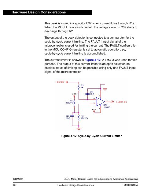
The output of the peak detector is connected to a comparator for the<br />
cycle-by-cycle current limiting. The FAULT1 input signal of the<br />
microcontroller is used for limiting the current. The FAULT configuration<br />
in the MCU CONFIG register is set to automatic operation; so,<br />
cycle-by-cycle current limiting is accomplished.<br />
The current limiter is shown in Figure 4-12. A LM393 was used for this<br />
purpose. The output of this current limiter is an open collector, so<br />
multiple inputs of limiting can be possible using only one FAULT input<br />
signal of the microcontroller.<br />
I_SENSE<br />
R32<br />
1K<br />
R5<br />
2.5K 1%<br />
VCC<br />
C44<br />
15pF<br />
6<br />
5<br />
+15V<br />
-<br />
+<br />
8 4<br />
7<br />
IC7B<br />
LM393D<br />
I_LIMIT_OC<br />
C28<br />
22pF<br />
R6<br />
10K 1%<br />
Figure 4-12. Cycle-by-Cycle Current Limiter<br />
DRM007<br />
BLDC Motor <strong>Co</strong>ntrol Board for Industrial and Appliance Applications<br />
66 Hardware Design <strong>Co</strong>nsiderations MOTOROLA


