Prisma II 1310 nm High Density Transmitter and Host Module ...
Prisma II 1310 nm High Density Transmitter and Host Module ...
Prisma II 1310 nm High Density Transmitter and Host Module ...

You also want an ePaper? Increase the reach of your titles
YUMPU automatically turns print PDFs into web optimized ePapers that Google loves.
Chapter 1 <strong>Module</strong> Introduction<br />
In Manual mode, an attenuator can be used to reduce RF power in an overdrive<br />
condition or to compensate for variations in transmitter gain. Any manual<br />
attenuator adjustments are reflected in the indicated RF drive level. It may be<br />
desirable to make such adjustments to compensate for power differences if the<br />
channel load differs from the specified value.<br />
In AGC mode, the microprocessor monitors the actual input composite power<br />
<strong>and</strong> adjusts the attenuator to maintain constant RF drive level into the laser<br />
diode.<br />
After the RF amplification <strong>and</strong> control stage, the signal is equalized <strong>and</strong> impedancematched,<br />
<strong>and</strong> then is sent to the laser. The optical output connector is located on the<br />
front panel of the module.<br />
The user can turn the laser on or off, adjust the drive level to the laser, <strong>and</strong> set alarm<br />
levels. The module can be controlled either locally using an ICIM front-panel<br />
interface, or remotely using LCI or TNCS software, CLI comm<strong>and</strong>s, or the ICIM Web<br />
Interface.<br />
<strong>High</strong> <strong>Density</strong> <strong>Transmitter</strong> Optical Output<br />
Laser Warning<br />
Depending on how you ordered your system, the optical output connectors may be<br />
either SC/APC, SC/UPC, or E2000/APC.<br />
WARNING:<br />
Avoid damage to your eyes! Do not look into any optical connector while the<br />
system is active. Even if the unit is off, there may still be hazardous optical<br />
levels present.<br />
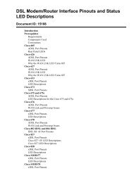
<strong>High</strong> <strong>Density</strong> <strong>Transmitter</strong> Block Diagram<br />
Broadcast RF<br />
Input<br />
Voltage<br />
Controlled<br />
Attenuator<br />
Predistortion<br />
DFB<br />
Laser<br />
Optical Output<br />
New Media<br />
( narrowcast)<br />
RF Input<br />
ICIM<br />
Front Panel<br />
( optional module)<br />
Front Panel<br />
RF<br />
Test Point<br />
Microprocessor<br />
LCI User<br />
Interface<br />
Connector<br />
( on chassis)<br />
TP202<br />
4 78-4021716-01 Rev C