Prisma II 1310 nm High Density Transmitter and Host Module ...
Prisma II 1310 nm High Density Transmitter and Host Module ...
Prisma II 1310 nm High Density Transmitter and Host Module ...

You also want an ePaper? Increase the reach of your titles
YUMPU automatically turns print PDFs into web optimized ePapers that Google loves.
Chapter 2 <strong>Module</strong> Installation<br />
For detailed information on ALARM IN <strong>and</strong> ALARM OUT connectors, see the<br />
<strong>Prisma</strong> <strong>II</strong> Chassis Installation <strong>and</strong> Operation Guide, part number 713375 or the <strong>Prisma</strong><br />
<strong>II</strong> XD Platform System Guide, part number 4021339.<br />
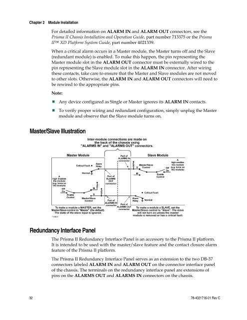
When a critical alarm occurs in a Master module, the Master turns off <strong>and</strong> the Slave<br />
(redundant module) is enabled. To make this happen, the pin representing the<br />
Master module slot in the ALARM OUT connector must be externally wired to the<br />
pin representing the Slave module slot in the ALARM IN connector. After wiring<br />
these contacts, take care to ensure that the Master <strong>and</strong> Slave modules are not moved<br />
to other slots. Otherwise, the ALARM IN <strong>and</strong> ALARM OUT connectors will need to<br />
be rewired to the appropriate pins.<br />
Note:<br />
Any device configured as Single or Master ignores its ALARM IN contacts.<br />
To verify proper wiring <strong>and</strong> redundant configuration, simply unplug the Master<br />
module <strong>and</strong> observe that the Slave module turns on.<br />
Master/Slave Illustration<br />
Redundancy Interface Panel<br />
The <strong>Prisma</strong> <strong>II</strong> Redundancy Interface Panel is an accessory to the <strong>Prisma</strong> <strong>II</strong> platform.<br />
It is intended to be used with the master/slave feature <strong>and</strong> the contact closure alarm<br />
feature of the <strong>Prisma</strong> <strong>II</strong> platform.<br />
The <strong>Prisma</strong> <strong>II</strong> Redundancy Interface Panel serves as an extension to the two DB-37<br />
connectors labeled ALARM IN <strong>and</strong> ALARM OUT on the connector interface panel<br />
of the chassis. The terminals on the redundancy interface panel are extensions of<br />
pins on the ALARMS OUT <strong>and</strong> ALARMS IN connectors on the chassis.<br />
32 78-4021716-01 Rev C