sPeCIAL ArABAL - ALUMINIUM-Nachrichten – ALU-WEB.DE
sPeCIAL ArABAL - ALUMINIUM-Nachrichten – ALU-WEB.DE
sPeCIAL ArABAL - ALUMINIUM-Nachrichten – ALU-WEB.DE

Create successful ePaper yourself
Turn your PDF publications into a flip-book with our unique Google optimized e-Paper software.
<strong><strong>ALU</strong>MINIUM</strong> INdUstry IN the GULf<br />
successful start-up of the fume treatment<br />
centre at ras Al Khair aluminium smelter<br />
J. de Weerdt, P. Klut; danieli Corus<br />
Two FTC’s were built in Ras Al Khair,<br />
Kingdom of Saudi Arabia, as part of the<br />
Ma’aden aluminium complex. These<br />
FTC’s treat the fumes of two anode<br />
bake furnaces that supply anodes to the<br />
740,000 tpy aluminium smelter. FTC 2<br />
was commissioned in October 2012 and<br />
is currently running at full capacity. The<br />
cold commissioning of FTC 1 was done<br />
in January 2013, and hot commissioning<br />
took place in June 2013. As with all startups,<br />
there were some challenges to overcome,<br />
but currently FTC 2 is fully operational<br />
and FTC 1 is running at about 50%<br />
of its capacity because not all fires at the<br />
anode bake furnace 1 are in operation<br />
yet. Both FTCs are performing satisfactory.<br />
FTC 2 performance tests have taken<br />
place in the first week of July 2013.<br />
The Ras Al Khair aluminium smelter project<br />
is a USD10.8 billion joint venture between<br />
Saudi Arabian Mining Company (Ma’aden)<br />
and Alcoa. The aim of the smelter project is<br />
to realise world’s largest and most efficient<br />
aluminium complex with a yearly capacity of<br />
740,000 tonnes. The project’s alumina refinery,<br />
aluminium smelter and rolling mill are located<br />
at Ras Al Khair, 90 km north of Jubail.<br />
The aluminium smelter consists of two potlines<br />
of 360 pots each, using AP37 technology.<br />
There are two anode bake furnaces, ABF 1<br />
having four fires and ABF 2 having three fires,<br />
that produce anodes for the potlines. Both<br />
ABF’s have their own dedicated FTC to treat<br />
the fumes from the fires. FTC 1 consists of<br />
six baghouses and four main exhaust fans (of<br />
which 3 duty and 1 standby) treating the fumes<br />
of ABF 1. FTC 2 consists of five baghouses and<br />
three main exhaust fans (of which 2 duty and<br />
1 standby) treating the fumes of ABF 2. Table<br />
1 summarises the process design data for FTC<br />
1 and FTC 2.<br />
The objective of the FTC’s is to meet the<br />
client requirements in terms of ease of operation,<br />
high online reliability, maintenance<br />
friendliness while performing to comply with<br />
the stringent local environmental legislations<br />
on airborne emissions. The fume composition<br />
and maximum emission levels are listed in<br />
Table 2.<br />
Type of pollutant<br />
the ftC design<br />
Fume composition<br />
[mg/Nm 3 ]<br />
Maximum<br />
emission<br />
[mg/Nm 3 ]<br />
Gaseous fluorides 0 <strong>–</strong> 200 < 0.5<br />
Particulate fluorides 0 <strong>–</strong> 50 < 0.6<br />
Total particulates 0 <strong>–</strong> 200 < 5.7<br />
Condensed soluble tars 0 <strong>–</strong> 200 < 1.7<br />
Table 2: Fume composition and maximum emission<br />
levels<br />
The most notable achievement in this project<br />
was the short time required for the engineering<br />
and fabrication of both FTC’s. The total time<br />
for the engineering of two complete FTC’s was<br />
only nine months, while only five month after<br />
placement of the purchase orders the first<br />
FTC 2 equipment arrived on site.<br />
Danieli Corus purchased equipment worldwide<br />
and transported it to site in order to meet<br />
the tight schedule. Despite the sometimes<br />
challenging custom clearance, availability of<br />
material within KSA, working pressure and<br />
deadlines that had to be met, all equipment<br />
arrived at site within a relatively short period<br />
of time.<br />
Furthermore, the equipment was supplied<br />
in large module delivery which had a major<br />
impact on site labour requirements since less<br />
site welding was required compared to combining<br />
a series of smaller components. Also,<br />
the complete piping system was prefabricated<br />
in order to reduce site labour required.<br />
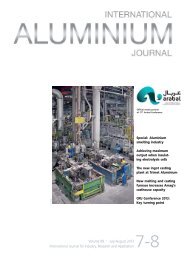
This type of modularisation in combination<br />
with the split of responsibilities between<br />
manufacturing and the erection could only<br />
be accomplished with a detailed 3D model<br />
to avoid interferences on site. A detailed 3D<br />
model for both FTC’s was made in which the<br />
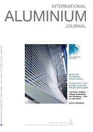
Fig. 1: Modular design, left <strong>–</strong> preassembled baghouse, right <strong>–</strong> fully fabricated cooling tower<br />
© Danieli Corus<br />
Process Variable FTC 1 FTC 2<br />
Fume volume (Am 3 /h) 245,000 180,000<br />
Fume temperature (°C) 220 220<br />
Underpressure at ABF (kPa) -2,000 -2,000<br />
Number of baghouses 6 5<br />
Number of main exhaust fans 3 + 1 2 + 1<br />
Alumina utilisation (t/hr) 6 4<br />
Table 1: FTC 1 and FTC 2 process design data<br />
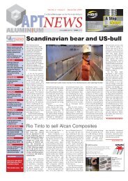
Fig. 2: Modular design, left <strong>–</strong> preassembled stack section in laydown area, right <strong>–</strong> installation of preassembled<br />
stack section<br />
50 <strong><strong>ALU</strong>MINIUM</strong> · 9/2013