PENELOPE 2003 - OECD Nuclear Energy Agency
PENELOPE 2003 - OECD Nuclear Energy Agency
PENELOPE 2003 - OECD Nuclear Energy Agency

Create successful ePaper yourself
Turn your PDF publications into a flip-book with our unique Google optimized e-Paper software.
5.4. Geometry definition file 165<br />
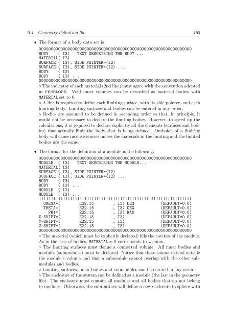
• The format of a body data set is<br />
0000000000000000000000000000000000000000000000000000000000000000<br />
BODY ( I3) TEXT DESCRIBING THE BODY ...<br />
MATERIAL( I3)<br />
SURFACE ( I3), SIDE POINTER=(I2)<br />
SURFACE ( I3), SIDE POINTER=(I2) ...<br />
BODY ( I3)<br />
BODY ( I3) ...<br />
0000000000000000000000000000000000000000000000000000000000000000<br />
◦ The indicator of each material (2nd line) must agree with the convention adopted<br />
in penelope. Void inner volumes can be described as material bodies with<br />
MATERIAL set to 0.<br />
◦ A line is required to define each limiting surface, with its side pointer, and each<br />
limiting body. Limiting surfaces and bodies can be entered in any order.<br />
◦ Bodies are assumed to be defined in ascending order so that, in principle, it<br />
would not be necessary to declare the limiting bodies. However, to speed up the<br />
calculations, it is required to declare explicitly all the elements (surfaces and bodies)<br />
that actually limit the body that is being defined. Omission of a limiting<br />
body will cause inconsistencies unless the materials in the limiting and the limited<br />
bodies are the same.<br />
• The format for the definition of a module is the following:<br />
0000000000000000000000000000000000000000000000000000000000000000<br />
MODULE ( I3) TEXT DESCRIBING THE MODULE...<br />
MATERIAL( I3)<br />
SURFACE ( I3), SIDE POINTER=(I2)<br />
SURFACE ( I3), SIDE POINTER=(I2) ...<br />
BODY ( I3)<br />
BODY ( I3) ...<br />
MODULE ( I3)<br />
MODULE ( I3) ...<br />
1111111111111111111111111111111111111111111111111111111111111111<br />
OMEGA=( E22.15 , I3) DEG (DEFAULT=0.0)<br />
THETA=( E22.15 , I3) DEG (DEFAULT=0.0)<br />
PHI=( E22.15 , I3) RAD (DEFAULT=0.0)<br />
X-SHIFT=( E22.15 , I3) (DEFAULT=0.0)<br />
Y-SHIFT=( E22.15 , I3) (DEFAULT=0.0)<br />
Z-SHIFT=( E22.15 , I3) (DEFAULT=0.0)<br />
0000000000000000000000000000000000000000000000000000000000000000<br />
◦ The material (which must be explicitly declared) fills the cavities of the module.<br />
As in the case of bodies, MATERIAL = 0 corresponds to vacuum.<br />
◦ The limiting surfaces must define a connected volume. All inner bodies and<br />
modules (submodules) must be declared. Notice that these cannot extend outside<br />
the module’s volume and that a submodule cannot overlap with the other submodules<br />
and bodies.<br />
◦ Limiting surfaces, inner bodies and submodules can be entered in any order.<br />
◦ The enclosure of the system can be defined as a module (the last in the geometry<br />
file). The enclosure must contain all modules and all bodies that do not belong<br />
to modules. Otherwise, the subroutines will define a new enclosure (a sphere with