PENELOPE 2003 - OECD Nuclear Energy Agency
PENELOPE 2003 - OECD Nuclear Energy Agency
PENELOPE 2003 - OECD Nuclear Energy Agency

You also want an ePaper? Increase the reach of your titles
YUMPU automatically turns print PDFs into web optimized ePapers that Google loves.
200 Chapter 6. Structure and operation of the code system<br />
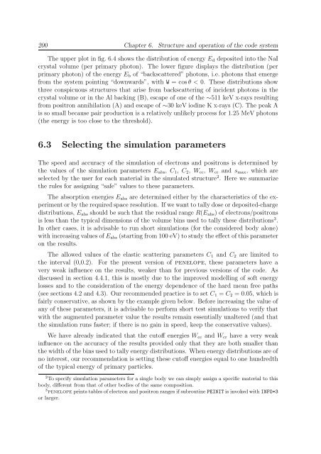
The upper plot in fig. 6.4 shows the distribution of energy E d deposited into the NaI<br />
crystal volume (per primary photon). The lower figure displays the distribution (per<br />
primary photon) of the energy E b of “backscattered” photons, i.e. photons that emerge<br />
from the system pointing “downwards”, with W = cos θ < 0. These distributions show<br />
three conspicuous structures that arise from backscattering of incident photons in the<br />
crystal volume or in the Al backing (B), escape of one of the ∼511 keV x-rays resulting<br />
from positron annihilation (A) and escape of ∼30 keV iodine K x-rays (C). The peak A<br />
is so small because pair production is a relatively unlikely process for 1.25 MeV photons<br />
(the energy is too close to the threshold).<br />
6.3 Selecting the simulation parameters<br />
The speed and accuracy of the simulation of electrons and positrons is determined by<br />
the values of the simulation parameters E abs , C 1 , C 2 , W cc , W cr and s max , which are<br />
selected by the user for each material in the simulated structure 2 . Here we summarize<br />
the rules for assigning “safe” values to these parameters.<br />
The absorption energies E abs are determined either by the characteristics of the experiment<br />
or by the required space resolution. If we want to tally dose or deposited-charge<br />
distributions, E abs should be such that the residual range R(E abs ) of electrons/positrons<br />
is less than the typical dimensions of the volume bins used to tally these distributions 3 .<br />
In other cases, it is advisable to run short simulations (for the considered body alone)<br />
with increasing values of E abs (starting from 100 eV) to study the effect of this parameter<br />
on the results.<br />
The allowed values of the elastic scattering parameters C 1 and C 2 are limited to<br />
the interval (0,0.2). For the present version of penelope, these parameters have a<br />
very weak influence on the results, weaker than for previous versions of the code. As<br />
discussed in section 4.4.1, this is mostly due to the improved modelling of soft energy<br />
losses and to the consideration of the energy dependence of the hard mean free paths<br />
(see sections 4.2 and 4.3). Our recommended practice is to set C 1 = C 2 = 0.05, which is<br />
fairly conservative, as shown by the example given below. Before increasing the value of<br />
any of these parameters, it is advisable to perform short test simulations to verify that<br />
with the augmented parameter value the results remain essentially unaltered (and that<br />
the simulation runs faster; if there is no gain in speed, keep the conservative values).<br />
We have already indicated that the cutoff energies W cc and W cr have a very weak<br />
influence on the accuracy of the results provided only that they are both smaller than<br />
the width of the bins used to tally energy distributions. When energy distributions are of<br />
no interest, our recommendation is setting these cutoff energies equal to one hundredth<br />
of the typical energy of primary particles.<br />
2 To specify simulation parameters for a single body we can simply assign a specific material to this<br />
body, different from that of other bodies of the same composition.<br />
3 penelope prints tables of electron and positron ranges if subroutine PEINIT is invoked with INFO=3<br />
or larger.