- Page 1 and 2:
Learning by Doing: CISCO Certified
- Page 3 and 4:
About the Author Matthew Basham is
- Page 5 and 6:
Acknowledgements Preface Table of C
- Page 7 and 8:
Basic Access Control Lists 342 Exte
- Page 9 and 10:
Searching CISCO for CCNA Test infor
- Page 11 and 12:
Figure 5—Scroll down to CCNA exam
- Page 13 and 14:
Objective: This lab is designed to
- Page 15 and 16:
g. If you really have some time to
- Page 17 and 18:
C:\ |___CDDROM\ |___MY_Documents\ |
- Page 19 and 20:
Sometimes we do not always know or
- Page 21 and 22:
find format keyb label mode more nl
- Page 23 and 24:
WINREP.EXE WINFILE.EXE WINHELP.EXE
- Page 25 and 26:
pause copy c:\temp\matt.txt c:\temp
- Page 27 and 28:
Cool Windows 95/98 Utilities KRNL38
- Page 29 and 30:
Changing TCP/IP Settings on Your Co
- Page 31 and 32:
Gateway Tab Figure 4—Putting in a
- Page 33 and 34:
Paper Lab: ICONS for Computer Diagr
- Page 35 and 36:
CISCO Net Ranger—CISCO security d
- Page 37 and 38:
Laptop—ditto. File server—Used
- Page 39 and 40:
Firewall—Network Address Translat
- Page 41 and 42:
Paper Lab: Proper Cable for the Pro
- Page 43 and 44:
Rollover (ro): Used for connecting
- Page 45 and 46:
Change hubs to switches: 38
- Page 47 and 48:
Add in a web access: DSU/CSU WWW 40
- Page 49 and 50:
4. Click on the file and print shar
- Page 51 and 52:
Figure 7—Selecting the options fo
- Page 53 and 54:
You should see something like this:
- Page 55 and 56:
purpose. Check your documentation.
- Page 57 and 58:
Now along the column headings we se
- Page 59 and 60:
Let’s try another one: 223. Start
- Page 61 and 62:
Then, using a different color marke
- Page 63 and 64:
Let me just walk through one more
- Page 65 and 66:
2 7 2 6 2 5 2 4 2 3 2 2 2 1 2 0 128
- Page 67 and 68:
For example, lets convert the binar
- Page 69 and 70:
To convert a large hexadecimal numb
- Page 71 and 72:
Network Data Link Physical Provides
- Page 73 and 74:
Encapsulation As we move down the O
- Page 75 and 76:
Session Transport Network Data Link
- Page 77 and 78:
Objective: To be able to learn more
- Page 79 and 80:
There are all kinds of other topolo
- Page 81 and 82:
Supplemental Lab or Challenge Activ
- Page 83 and 84:
The Start of Frame Delimiter (SOF)
- Page 85 and 86:
The Control (con) is 1 byte long an
- Page 87 and 88:
The Options (Opt) field can vary in
- Page 89 and 90:
only one port at a time. The hub al
- Page 91 and 92:
1 3 5 7 Workstation Workstation Wor
- Page 93 and 94:
Supplemental Labs or Challenge Acti
- Page 95 and 96:
9. Collision Domains: ____________
- Page 97 and 98:
Paper Lab: Subnetting Objective: To
- Page 99 and 100:
12. Routers pass packets between __
- Page 101 and 102:
2. Which of the following dotted no
- Page 103 and 104:
18. Select the IP address for the s
- Page 105 and 106:
12. What is the decimal to binary c
- Page 107 and 108: 4. How many possible subnets can be
- Page 109 and 110: 16. How would the host field be exp
- Page 111 and 112: Subnet masking 1. How would the sub
- Page 113 and 114: Whole enchilada problems 1. Which o
- Page 115 and 116: Objective: To learn how to design n
- Page 117 and 118: Subnetting Example: John’s Brewho
- Page 119 and 120: Intermediate DOS Lab: Troubleshooti
- Page 121 and 122: 7. We know we have good connections
- Page 123 and 124: DHCP Lab Objective: To learn about
- Page 125 and 126: 5. Notice how our address may diffe
- Page 127 and 128: Free Protocol Inspector Objective:
- Page 129 and 130: Objective: To learn how to use a pr
- Page 131 and 132: Notice how we have three frames wit
- Page 133 and 134: 5. Type cd pub to change to the pub
- Page 135 and 136: Protocols and the OSI Model Objecti
- Page 137 and 138: DECnet Suite OSI Model 7 Protocol 6
- Page 139 and 140: Layer 2 Technologies: LAN’s OSI M
- Page 141 and 142: Supplemental Labs or Challenge Acti
- Page 143 and 144: Once you click “connect” you sh
- Page 145 and 146: Fun Ports to Surf with Telnet To op
- Page 147 and 148: 6. Make sure you have the following
- Page 149 and 150: (Step 1) Configure a connection on
- Page 151 and 152: . Double-click on “dial-up networ
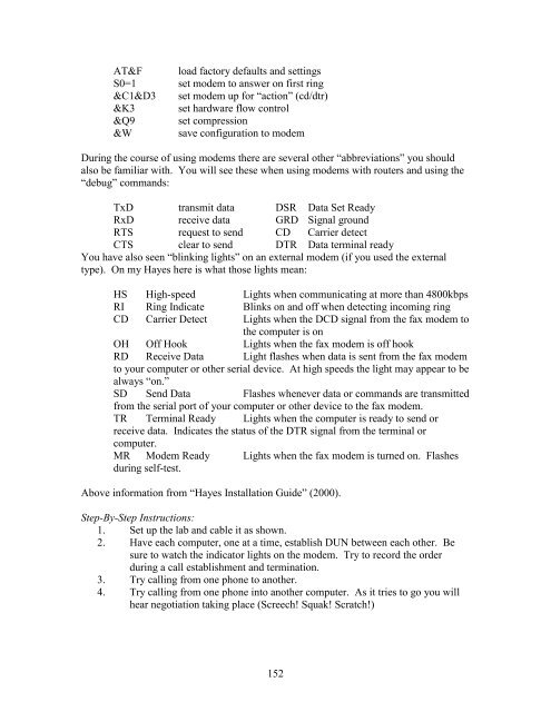
- Page 153 and 154: Step-By-Step Instructions: 1. You a
- Page 155 and 156: Figure 5d—Isn’t that nice? 4. C
- Page 157: Your Modem and You Objective: This
- Page 161 and 162: Part 2: Basic Routing I 154
- Page 163 and 164: More importantly to you right now i
- Page 165 and 166: Ethernet Console AUX Power Power Po
- Page 167 and 168: Objective: To become familiar with
- Page 169 and 170: 9. Write down what you see on the w
- Page 171 and 172: outer#terminal history size 5 17. U
- Page 173 and 174: Other modes you may use include: co
- Page 175 and 176: Objectives: To more fully understan
- Page 177 and 178: So let’s look at a boot sequence
- Page 179 and 180: Step-by-Step Instructions: 1. Hook
- Page 181 and 182: NVRAM Flash RAM/DRAM ROM CPU Serial
- Page 184 and 185: Basic Router Configuration Objectiv
- Page 186 and 187: 8. Once you have determined that yo
- Page 188 and 189: Basic Rip Objectives: To learn abou
- Page 190 and 191: It’s ok if you see it, but you pr
- Page 192 and 193: Gateway of last resort is not set C
- Page 194 and 195: Supplemental Lab or Challenge Activ
- Page 196 and 197: Step-by-Step Instructions: 1. Troub
- Page 198 and 199: Input queue: 0/75/0 (size/max/drops
- Page 200 and 201: 1 192.168.30.2 16 msec 16 msec * Ra
- Page 202 and 203: 5. Finally, do not forget about tho
- Page 204 and 205: Loopback Interfaces Objectives: To
- Page 206 and 207: 2. We can use a loopback interface
- Page 208 and 209:
C:\WINDOWS\Desktop>ping 22.22.22.22
- Page 210 and 211:
Basic RIP with Protocol Inspector O
- Page 212 and 213:
5. Wait two minutes. Remember, you
- Page 214 and 215:
Router Telnet Lab Objective: To lea
- Page 216 and 217:
william#debug telnet Incoming Telne
- Page 218 and 219:
Addressing: Routers Hostnames Phibe
- Page 220 and 221:
On Optik you should see: optik#debu
- Page 222 and 223:
Scenario 3: Hostnames Phiber Optik
- Page 224 and 225:
5. Setup the workstations with IP a
- Page 226 and 227:
RIP metrics and the Limitations of
- Page 228 and 229:
Interface Send Recv Key-chain Ether
- Page 230 and 231:
Step-by-Step Instructions: 1. Cable
- Page 232 and 233:
Subnetting with DHCP Objectives: To
- Page 234 and 235:
Objective: To learn how to implemen
- Page 236 and 237:
So What Have I Learned Here? In thi
- Page 238 and 239:
Workstations A B IP 161.20.2.2 161.
- Page 240 and 241:
Now let’s explore some of the oth
- Page 242 and 243:
Overcoming Problems with Routing Lo
- Page 244 and 245:
RIP Version 2 and Redistribution wi
- Page 246 and 247:
9. Use your knowledge of debug comm
- Page 248 and 249:
Prompt Command Shortcut Description
- Page 250 and 251:
Design a network using VLSM and the
- Page 252 and 253:
Troubleshooting scenarios for Part
- Page 254 and 255:
Switch Maintenance Objective: In th
- Page 256 and 257:
Remember how we just put in a passw
- Page 258 and 259:
Just click on “yes” to clear th
- Page 260 and 261:
Step-By-Step Instructions: 1. You s
- Page 262 and 263:
Figure 2—STP showing cost of 10.
- Page 264 and 265:
Intermediate STP Objective: To be a
- Page 266 and 267:
connection to the root switch. That
- Page 268 and 269:
8. Change the cost of port 7 back t
- Page 270 and 271:
4. Now we need to assign ports to t
- Page 272 and 273:
c. Click on [A] for add a VLAN (thi
- Page 274 and 275:
Mixing it up: VLAN’s with STP Obj
- Page 276 and 277:
Subnetting Example: ABC Packaging O
- Page 278 and 279:
4. Stop the capture. You should see
- Page 280 and 281:
Part 3 Command Review Objective: To
- Page 282 and 283:
Whole Enchilada/Crazy Insano Lab #1
- Page 284 and 285:
Whole Enchilada/Crazy Insano Lab #3
- Page 286 and 287:
Whole Enchilada/Crazy Insano Lab #5
- Page 288 and 289:
Paper Lab: CISCO Three-Layer Hierar
- Page 290 and 291:
Protocol Deathmatch: RIP versus RIP
- Page 292 and 293:
company and control access between
- Page 294 and 295:
Supplemental Lab or Challenge Activ
- Page 296 and 297:
Step-By-Step Instructions: 1. Set u
- Page 298 and 299:
Guest Router Name Derivation In 199
- Page 300 and 301:
Workstations A B IP 200.150.100.2 2
- Page 302 and 303:
I 202.150.100.0/24 [100/8576] via 2
- Page 304 and 305:
Here we can see the entry for netwo
- Page 306 and 307:
Redistribution of IGRP and RIP Obje
- Page 308 and 309:
3. Now we can see how this affects
- Page 310 and 311:
dennis(config)#router rip dennis(co
- Page 312 and 313:
Gateway of last resort is not set I
- Page 314 and 315:
to add the extra metrics statements
- Page 316 and 317:
7. Notice the reachable/not reachab
- Page 318 and 319:
Supplemental Lab or Challenge Activ
- Page 320 and 321:
(VLSM/CIDR). OSPF on a wider scale
- Page 322 and 323:
wash# leung#sh ip ospf Routing Proc
- Page 324 and 325:
Border Gateway Protocol (BGP) Objec
- Page 326 and 327:
3. Let’s add in the BGP. It too u
- Page 328 and 329:
BGP table version is 24, local rout
- Page 330 and 331:
What time interval for each protoco
- Page 332 and 333:
Basic IP/IPX with Dynamic Routing O
- Page 334 and 335:
gibson#ping ipx 0000.1234.1111 % Un
- Page 336 and 337:
gibson#debug ipx sap ? activity IPX
- Page 338 and 339:
IPX Lab Diagram: network 100 enc SA
- Page 340 and 341:
7. Now let’s try that ping IPX ag
- Page 342 and 343:
Objective: To learn how to create w
- Page 344 and 345:
Paper Lab: Access Control Lists Obj
- Page 346 and 347:
Now we just need to do the second s
- Page 348 and 349:
Now let’s try to “free-hand”
- Page 350 and 351:
4. Make four text files and put one
- Page 352 and 353:
10. Try the shortcut to the 192.168
- Page 354 and 355:
Objective: To implement an extended
- Page 356 and 357:
8. Now let’s try the show access
- Page 358 and 359:
Objective: To implement a named acc
- Page 360 and 361:
Supplemental Lab or Challenge Activ
- Page 362 and 363:
actually build a mini-protocol insp
- Page 364 and 365:
Log Buffer (4096 bytes): 00:27:14:
- Page 366 and 367:
Firewall Basics using Reflexive ACL
- Page 368 and 369:
7. Even though that ACL works let
- Page 370 and 371:
Prompt Command Shortcut Description
- Page 372 and 373:
Whole Enchilada/Crazy Insano Lab #2
- Page 374 and 375:
Registering for Your CCNA Exam Obje
- Page 376 and 377:
3. Configure the router to receive
- Page 378 and 379:
Point-to-Point Protocol (PPP) Objec
- Page 380 and 381:
MTU 1500 bytes, BW 128 Kbit, DLY 20
- Page 382 and 383:
So what have I learned here? In thi
- Page 384 and 385:
PAP (Password Authentication Protoc
- Page 386 and 387:
00:54:36: Se0/0 IPCP: O CONFREQ [Cl
- Page 388 and 389:
4. Let’s turn off debugging. Use
- Page 390 and 391:
20. 01:24:46: Se0/1 LCP: MagicNumbe
- Page 392 and 393:
“real-world” scenario. Undo all
- Page 394 and 395:
Remote Access DUN with PPP Encapsul
- Page 396 and 397:
lord(config)#ipx routing 0000.BBBB.
- Page 398 and 399:
Setting up a Router to be a Frame R
- Page 400 and 401:
Objective: To learn how to set up a
- Page 402 and 403:
turner#sh frame-relay pvc PVC Stati
- Page 404 and 405:
Step-By-Step Instructions: 1. Cable
- Page 406 and 407:
Fully-Meshed Frame Relay with 3 Rou
- Page 408 and 409:
Shadow 16 17 18 18 Diekman 17 16 Kn
- Page 410 and 411:
interface connections for #16 and #
- Page 412 and 413:
Frame Relay Operation and Troublesh
- Page 414 and 415:
network we will see all but our own
- Page 416 and 417:
7. Wrong ip address/mask Here I jus
- Page 418 and 419:
outer#sh frame map Serial0/0 (up):
- Page 420 and 421:
3. Configure the ISDN interface on
- Page 422 and 423:
Challenge Lab or Supplemental Activ
- Page 424 and 425:
3. Configure the ISDN interface on
- Page 426 and 427:
00:21:08: %LINEPROTO-5-UPDOWN: Line
- Page 428 and 429:
Data Link Layer Two things happen h
- Page 430 and 431:
00:13:27: %LINEPROTO-5-UPDOWN: Line
- Page 432 and 433:
In line 1 we see our Q931 requestin
- Page 434 and 435:
Type escape sequence to abort. Send
- Page 436 and 437:
36. IPCP: Install route to 192.168.
- Page 438 and 439:
Last C/I to ISDN transceiver: AI:Ac
- Page 440 and 441:
kissane#sh controller bri BRI unit
- Page 442 and 443:
05:04:35: BR0/0:2 DDR: disconnectin
- Page 444 and 445:
Type escape sequence to abort. Send
- Page 446 and 447:
Sending 5, 100-byte ICMP Echos to 1
- Page 448 and 449:
kissane#debug ppp nego PPP protocol
- Page 450 and 451:
kissane#debug ppp nego PPP protocol
- Page 452 and 453:
06:47:25: BR0/0:1 PPP: Treating con
- Page 454 and 455:
Step-By-Step Instructions: 1. Confi
- Page 456 and 457:
7. Try to ping the loopback. You sh
- Page 458 and 459:
Frame Relay with ISDN Backup Object
- Page 460 and 461:
So what have I learned here? In thi
- Page 462 and 463:
Prompt Command Shortcut Description
- Page 464 and 465:
Coming In the Next Version of the T
- Page 466:
Did you like this book? There’s m