Installation Notes - USP Connectors
Installation Notes - USP Connectors
Installation Notes - USP Connectors

Create successful ePaper yourself
Turn your PDF publications into a flip-book with our unique Google optimized e-Paper software.
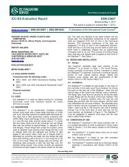
Bolted Glulam Beam Hangers – KEG, KLEG, & KMEG series<br />
Bolt-only fastening, heavy steel construction, and a<br />
continuous top flange allow the KLEG, KMEG, and<br />
KEG products to have high load capacities.<br />
KLEG – (4) bolt light-duty hanger.<br />
KMEG – (6) bolt medium-duty hanger.<br />
KEG – (8) bolt heavy-duty hanger.<br />
3˝<br />
3˝<br />
W<br />
L<br />
D<br />
4˝<br />
3˝<br />
TF<br />
8 1 /4˝<br />
H<br />
EWP Hangers<br />
© Copyright 2013 <strong>USP</strong> Structural <strong>Connectors</strong> ®<br />
Materials: See chart<br />
Finish: <strong>USP</strong> primer<br />
Options: See Specialty Options Chart.<br />
Codes: Load values are derived from data<br />
submitted to various North American<br />
building code evaluators.<br />
Beam height dimension (H) must<br />
be specified when ordering.<br />
<strong>Installation</strong>:<br />
• Use all specified fasteners. See Product <strong>Notes</strong>,<br />
page 10.<br />
• Bolts are not supplied unless ordered separately.<br />
Bolts provided by other suppliers must meet or<br />
exceed ASTM A 307 Grade A, or ASME SAE Grade 2,<br />
or better.<br />
• Minimum header height is 10˝ for the KLEG;<br />
13˝ for the KMEG; 20˝ for the KEG.<br />
4˝<br />
4˝<br />
W<br />
KLEG3<br />
L<br />
4˝<br />
4˝<br />
4˝<br />
4˝<br />
D<br />
KEG5<br />
TF<br />
17 1 /2˝<br />
H<br />
3˝<br />
3˝<br />
Typical KLEG5<br />
installation<br />
L<br />
D<br />
KMEG5<br />
TH<br />
4˝<br />
3˝<br />
3˝<br />
11 1 /4˝<br />
H<br />
Steel Gauge Dimensions (in) Fastener Schedule<br />
Factored Resistance 1<br />
Header Joist<br />
DF-L<br />
S-P-F<br />
Beam <strong>USP</strong><br />
Top U-<br />
Bolt Bolt<br />
Vertical 100% Uplift 115% 2 Vertical 100% Uplift 115% 2<br />
Width Stock No. Ref. No Flange Strap W H 3 D TF L Qty Dia. Qty Dia. Application Lbs kN Lbs kN Lbs kN Lbs kN<br />
3-1/8 KLEG3 LEG3 7 7 3-1/4 specify 6 2-1/2 12 4 3/4 2 3/4<br />
With Top Flange 15060 66.99 4040 17.97 12950 57.61 3475 15.46<br />
Without Top Flange 5125 22.80 4040 17.97 4410 19.62 3475 15.46<br />
KLEG5 LEG5 7 7 5-1/4 specify 6 2-1/2 12 4 3/4 2 3/4<br />
With Top Flange 15060 66.99 5910 26.29 12950 57.61 5085 22.62<br />
Without Top Flange 5125 22.80 5910 26.29 4410 19.62 5085 22.62<br />
5-1/8 KMEG5 MEG5 7 7 5-1/4 specify 6 2-1/2 12 6 3/4 2 3/4<br />
With Top Flange 17555 78.09 5915 26.31 15095 67.15 5085 22.62<br />
Without Top Flange 7620 33.90 5915 26.31 6555 29.16 5085 22.62<br />
KEG5 EG5 1/4 7 5-1/4 specify 6 2-1/2 12 8 1 2 1<br />
With Top Flange 23125 102.87 7625 33.92 19890 88.48 6560 29.18<br />
Without Top Flange 13190 58.67 7625 33.92 11345 50.47 6560 29.18<br />
KLEG7 LEG7 7 7 6-7/8 specify 6 2-1/2 12 4 3/4 2 3/4<br />
With Top Flange 15060 66.99 5910 26.29 12950 57.61 5085 22.62<br />
Without Top Flange 5125 22.80 5910 26.29 4410 19.62 5085 22.62<br />
6-3/4 KMEG7 MEG7 7 7 6-7/8 specify 6 2-1/2 12 6 3/4 2 3/4<br />
With Top Flange 17555 78.09 5910 26.29 15095 67.15 5085 22.62<br />
Without Top Flange 7620 33.90 5910 26.29 6555 29.16 5085 22.62<br />
KEG7 EG7 1/4 7 6-7/8 specify 6 2-1/2 13-1/2 8 1 2 1<br />
With Top Flange 24410 108.59 9595 42.68 20995 93.39 8250 36.70<br />
Without Top Flange 13235 58.87 9595 42.68 11380 50.62 8250 36.70<br />
8-3/4 KEG9 EG9 1/4 7 8-7/8 specify 6 2-1/2 15-1/2 8 1 2 1<br />
With Top Flange 26100 116.10 9580 42.62 22445 99.84 8240 36.65<br />
Without Top Flange 13270 59.03 9580 42.62 11410 50.76 8240 36.65<br />
10-3/4 KEG11 -- -- 1/4 7 10-7/8 specify 6 2-1/2 17-1/2 8 1 2 1<br />
With Top Flange 27785 123.60 9570 42.57 23895 106.29 8230 36.61<br />
Without Top Flange 13300 59.16 9570 42.57 11440 50.89 8230 36.61<br />
1) Factored resistances are for a supporting member with a width of 5-1/2", and 460 psi perpendicular to grain loading in single shear.<br />
2) Factored uplift resistances have been increased 15% for short-term loads such as wind and earthquake; reduce for other load durations in accordance with the code.<br />
3) "Specify" denotes the required supported beam height that must be specified at the time of ordering.<br />
Specialty Options Chart – refer to Specialty Options pages 210 and 212 for additional details.<br />
Option Skewed 3 Sloped Seat Top Flange Offset 1,2<br />
Range <br />
<br />
-- --<br />
Factored<br />
Resistance<br />
Ordering<br />
KLEG - 14400 lbs. Max.<br />
KMEG - 14400 lbs. Max.<br />
KEG - 20520 lbs. Max.<br />
Add SK, angle required,<br />
and right (R) or left (L),<br />
to product number.<br />
Ex. KLEG3H112-SK45R<br />
KLEG - 13920 lbs. Max.<br />
KMEG - 13920 lbs. Max.<br />
KEG - 13920 lbs. Max.<br />
Add SL, slope required,<br />
and up (U) or down (D),<br />
to product number.<br />
Ex. KLEG3H112-SL30D<br />
KLEG - 8160 lbs. Max.<br />
<br />
KMEG - 8160 lbs. Max.<br />
<br />
Add OS, and<br />
right (R) or left (L),<br />
to product number.<br />
Ex. KLEG3H112-OSL<br />
1) Top flange offset hangers may not be skewed. 3) Carried member must have square cut end on skewed option. Refer to<br />
2) Top flange offset option is not available for KEG mode Typical PHXU hanger, skewed, left shown, Type B illustration on page 212.<br />
1-800-328-5934 • www.<strong>USP</strong>connectors.com 147<br />
<strong>USP</strong>2240-131