Installation Notes - USP Connectors
Installation Notes - USP Connectors
Installation Notes - USP Connectors

You also want an ePaper? Increase the reach of your titles
YUMPU automatically turns print PDFs into web optimized ePapers that Google loves.
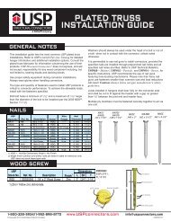
Truss Brace & Spacer (Stabilizer TM )<br />
The Stabilizer Truss Brace & Spacer provides temporary construction bracing in<br />
the roof and ceiling planes, as well as permanent lateral bracing for webs as<br />
specified by your truss engineering.<br />
The Stabilizer is easily installed by embedding the patented MII 20 teeth on the<br />
top flange straight into the edge of the truss member to be braced with a framing<br />
hammer. The side tabs are then secured by driving the teeth into the face of the<br />
truss member being braced.<br />
24 o.c.<br />
Odd<br />
Spacing<br />
Plated Truss<br />
Materials: 20 gauge<br />
Finish: G60 galvanizing<br />
Codes: Load values are derived from data submitted to various North<br />
American building code evaluators.<br />
<strong>Installation</strong>:<br />
• Use 31-16 for standard 16˝ o.c. spacing and 31-24 for standard 24˝ o.c. spacing.<br />
For odd spacing, cut and insert a solid block between the trusses.<br />
• Typically, The Stabilizer is installed at 6´– 8´ centres along the roof plane and<br />
10´– 15´ along the ceiling plane. (Refer to engineering specifications BCSI 1-03,<br />
published by The Truss Plate Institute for specific bracing requirements.)<br />
• The Stabilizer must be supplemented with diagonal bracing in the roof and ceiling<br />
planes and cross bracing in the web plane at required intervals.<br />
• Web forces are not to exceed 8000 lbs.<br />
• The Stabilizer is properly installed when the top flap and side tabs are flush<br />
with the member being braced.<br />
Important: The erection contractor is responsible for determining and<br />
installing the temporary bracing for the structure, including the trusses. It is<br />
most important for the installer to provide adequate means for bracing the first<br />
truss installed. The performance of the entire bracing system depends on the<br />
adequacy of the ground bracing or other means of bracing the first group of<br />
trusses installed. The building designer is responsible for the permanent<br />
bracing design of the overall structure including the truss. This includes the<br />
design of required supplemental diagonal and cross bracing.<br />
Temporary Construction<br />
Bracing <strong>Installation</strong><br />
1 3 /8˝<br />
Flap<br />
25 1 /4˝<br />
31-24 Stabilizer<br />
22 1 /2˝<br />
© Copyright 2013 <strong>USP</strong> Structural <strong>Connectors</strong> ®<br />
Hammer here<br />
Side view<br />
1˝<br />
7/8˝<br />
73.19º<br />
Hammer here<br />
Chord<br />
attachment detail<br />
Web bracing<br />
installation<br />
Top view<br />
1 1 /2˝<br />
1 3 /8˝<br />
Standard Mil 20 punch<br />
<strong>USP</strong><br />
Stock No.<br />
O.C.<br />
Factored Axial Loads (Lbs.)<br />
Steel Spacing<br />
Tension<br />
Ref. No. Gauge (in) Tension with Fastener Compression<br />
1) 1 pound = 4.448N<br />
31-16 TSBR2-16 20 16<br />
31-24 TSBR2-24 20 24<br />
152 222 608<br />
2) Fastener shall be (1) 8d or 10d common wire nail inserted through nail slot.<br />
New products or updated product information are designated in red font.<br />
End view<br />
1 3 /8˝<br />
Tab<br />
1 3 /8˝<br />
7/8˝<br />
1˝<br />
1/4˝<br />
1 1 /2˝<br />
180<br />
1-800-328-5934 • www.<strong>USP</strong>connectors.com