Installation Notes - USP Connectors
Installation Notes - USP Connectors
Installation Notes - USP Connectors

Create successful ePaper yourself
Turn your PDF publications into a flip-book with our unique Google optimized e-Paper software.
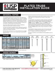
Wet Post Anchors – WAS & WE series<br />
WAS – A formed base providing a 1˝ stand-off with high<br />
bearing capacity.<br />
Uplift<br />
© Copyright 2013 <strong>USP</strong> Structural <strong>Connectors</strong>®<br />
WE – A formed, one-piece design. Includes embossing for<br />
additional lateral strength.<br />
Materials: See chart<br />
Finish: G90 galvanizing<br />
Options: WAS44, WAS46, WAS66, WE44, WE46,<br />
& WE66 are available in Triple Zinc. To<br />
order, add TZ to stock number, as in<br />
WAS44-TZ.<br />
WAS44, WAS66, and WE44 are available<br />
in Hot-dip galvanized. To order, add HDG<br />
to stock number, as in WE44-HDG.<br />
Codes: Load values are derived from data<br />
submitted to various North American<br />
building code evaluators.<br />
<strong>Installation</strong>:<br />
• Use all specified fasteners. See Product <strong>Notes</strong>,<br />
page 10.<br />
• Insert into wet concrete after the pour. For the WE, embed<br />
the anchor so that the base plate is flush with the surface<br />
of the concrete. For the WAS, embed the anchor until the<br />
concrete surface meets the bottom edge of the stand off<br />
base legs. This will provide a 1˝ stand-off where required.<br />
A 2˝ minimum edge distance is required to achieve<br />
factored resistance.<br />
• Not recommended for fence posts or other<br />
unrestrained (not fixed or fastened at top) applications.<br />
These anchors are not designed to resist overturning<br />
(moment) loads.<br />
H 1<br />
H 2<br />
Typical WE<br />
installation<br />
L<br />
WE<br />
2˝ Min.<br />
edge distance<br />
W 1<br />
2˝ Min.<br />
edge<br />
distance<br />
11 3 /16˝<br />
F 1<br />
F 2<br />
Typical WAS<br />
installation<br />
W 1<br />
H 1<br />
W 2<br />
H 2<br />
WAS<br />
L<br />
1˝ Stand-off<br />
plate<br />
Steel Gauge<br />
Dimensions (in)<br />
Fastener<br />
Factored Resistance 4,5<br />
Post <strong>USP</strong><br />
Schedule 3,5,6<br />
Wood Bearing 100% F1 (115%) 1 F2 (115%) 1 Uplift (115%) 1<br />
Size Stock No. Ref. No. Base Strap W1 W2 H1 H2 2 L Qty Type Species Lbs kN Lbs kN Lbs kN Lbs kN<br />
WE44 PB44 12 12 -- -- <br />
12 16d<br />
DF-L -- -- -- -- 1415 6.29 1470 6.54 1750 7.78<br />
S-P-F -- -- -- -- 1215 5.40 1265 5.63 1505 6.69<br />
2 <br />
DF-L -- -- -- -- 1135 5.05 1270 5.65 1780 7.92<br />
S-P-F -- -- -- -- 975 4.34 1090 4.85 1530 6.81<br />
<br />
DF-L -- -- -- -- 1470 6.54 1415 6.29 1750 7.78<br />
WE44R PB44R 12 12 4 -- -- 5 12 16d<br />
Rough<br />
S-P-F -- -- -- -- 1265 5.63 1215 5.40 1505 6.69<br />
WE46 PB46 12 12 -- -- <br />
12 16d<br />
DF-L -- -- -- -- 1415 6.29 1470 6.54 1750 7.78<br />
S-P-F -- -- -- -- 1215 5.40 1265 5.63 1505 6.69<br />
2 <br />
DF-L -- -- -- -- 1135 5.05 1270 5.65 1780 7.92<br />
S-P-F -- -- -- -- 975 4.34 1090 4.85 1530 6.81<br />
<br />
DF-L -- -- -- -- 1470 6.54 1415 6.29 1750 7.78<br />
WE46R -- -- 12 12 6 -- -- 5 12 16d<br />
Rough<br />
S-P-F -- -- -- -- 1265 5.63 1215 5.40 1505 6.69<br />
WE66 PB66 12 12 -- -- 5 12 16d<br />
DF-L -- -- -- -- -- -- -- -- 2790 12.41 2615 11.63<br />
S-P-F -- -- -- -- -- -- -- -- 2400 10.68 2250 10.01<br />
<br />
DF-L -- -- -- -- -- -- -- -- 2790 12.41 2615 11.63<br />
WE66R PB66R 12 12 6 -- -- 5 12 16d<br />
Rough<br />
S-P-F -- -- -- -- -- -- -- -- 2400 10.68 2250 10.01<br />
<br />
<br />
<br />
WAS44<br />
WAS46<br />
WAS66<br />
PBS44A<br />
PBS46<br />
PBS66<br />
16<br />
12<br />
12<br />
14<br />
14<br />
12<br />
<br />
<br />
<br />
<br />
<br />
<br />
<br />
<br />
<br />
<br />
<br />
5<br />
<br />
<br />
<br />
14<br />
14<br />
14<br />
16d<br />
16d<br />
16d<br />
DF-L<br />
DF-L<br />
DF-L<br />
9755<br />
19895<br />
23045<br />
43.39<br />
88.50<br />
102.51<br />
1750<br />
1750<br />
2615<br />
7.78<br />
7.78<br />
11.63<br />
1620<br />
1620<br />
1915<br />
7.21<br />
7.21<br />
8.52<br />
3235<br />
3235<br />
3420<br />
14.39<br />
14.39<br />
15.21<br />
S-P-F<br />
S-P-F<br />
S-P-F<br />
8390<br />
17110<br />
19820<br />
37.32<br />
76.11<br />
88.17<br />
1505<br />
1505<br />
2250<br />
6.69<br />
6.69<br />
10.01<br />
1395<br />
1395<br />
1645<br />
6.21<br />
6.21<br />
7.32<br />
2780<br />
2780<br />
2940<br />
12.37<br />
12.37<br />
13.08<br />
2<br />
2<br />
2<br />
<br />
<br />
<br />
DF-L<br />
DF-L<br />
DF-L<br />
9755<br />
19895<br />
23045<br />
43.39<br />
88.50<br />
102.51<br />
1760<br />
1850<br />
2695<br />
7.83<br />
8.23<br />
11.99<br />
1620<br />
1620<br />
1915<br />
7.21<br />
7.21<br />
8.52<br />
3235<br />
3235<br />
4530<br />
14.39<br />
14.39<br />
20.15<br />
S-P-F<br />
S-P-F<br />
S-P-F<br />
8390<br />
17110<br />
19820<br />
37.32<br />
76.11<br />
88.17<br />
1515<br />
1590<br />
2320<br />
6.74<br />
7.07<br />
10.32<br />
1395<br />
1395<br />
1645<br />
6.21<br />
6.21<br />
7.32<br />
2780<br />
2780<br />
3895<br />
12.37<br />
12.37<br />
17.33<br />
1) Factored resistances have been increased 15% for short-term loads such as wind and earthquake; reduce for other load durations in accordance with the code.<br />
2) H2 is mimimum embedment length of anchor into concrete.<br />
3) Minimum nail embedment shall be 8 nail diameters (typ).<br />
4) Minimum concrete compressive strength shall be 2,000 psi at 28 days.<br />
5) Factored resistances are based on the use of either nails or bolts; nail and bolt values cannot be combined.<br />
6) NAILS:<br />
1-800-328-5934 • www.<strong>USP</strong>connectors.com 53<br />
<strong>USP</strong>2240-131<br />
Caps & Bases