Installation Notes - USP Connectors
Installation Notes - USP Connectors
Installation Notes - USP Connectors

Create successful ePaper yourself
Turn your PDF publications into a flip-book with our unique Google optimized e-Paper software.
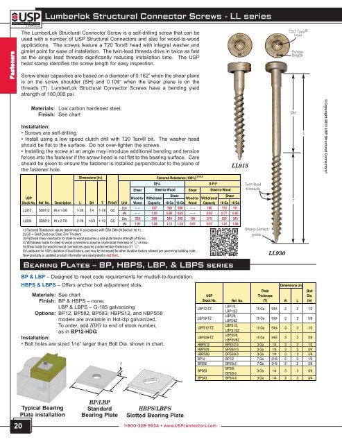
Lumberlok Structural Connector Screws - LL series<br />
Fasteners<br />
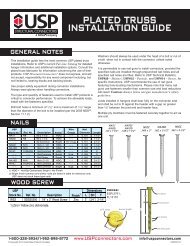
The LumberLok Structural Connector Screw is a self-drilling screw that can be<br />
used with a number of <strong>USP</strong> Structural <strong>Connectors</strong> and also for wood-to-wood<br />
applications. The screws feature a T20 Torx® head with integral washer and<br />
gimlet point for ease of installation. The twin-lead threads drive in twice as fast<br />
as the single lead threads significantly reducing installation time. The <strong>USP</strong><br />
head stamp identifies the screw length for easy inspection.<br />
Screw shear capacities are based on a diameter of 0.162” when the shear plane<br />
is on the screw shoulder (SH) and 0.109” when the shear plane is on the<br />
threads (T). LumberLok Structural Connector Screws have a bending yield<br />
strength of 180,000 psi.<br />
T20 Torx ®<br />
head<br />
Screw<br />
length<br />
Materials: Low carbon hardened steel.<br />
Finish: See chart<br />
<strong>Installation</strong>:<br />
• Screws are self-drilling.<br />
• Install using a low speed clutch drill with T20 Torx® bit. The washer head<br />
should be flat to the surface. Do not over-tighten the screws.<br />
• Installing the screw at an angle may introduce additional bending and tension<br />
forces into the fastener if the screw head is not flat to the bearing surface. Care<br />
should be given to ensure the fastener is installed perpendicular to the plane of<br />
the fastener hole.<br />
LL915<br />
SH<br />
L<br />
© Copyright 2013 <strong>USP</strong> Structural <strong>Connectors</strong> ®<br />
Dimensions (in.)<br />
<strong>USP</strong><br />
Wood-to- Withdrawal<br />
Shear<br />
Wood-to- Withdrawal<br />
Shear<br />
Stock No. Ref. No. Description L SH T Finish 2 Unit Wood Capacity 18 Ga 16 Ga Wood Capacity 18 Ga 16 Ga<br />
LL915<br />
LL930<br />
SD9112<br />
SD9212<br />
#9 x 1-3/8<br />
#9 x 2-7/8<br />
1-3/8<br />
2-7/8<br />
1/4<br />
1-3/8<br />
1-1/8<br />
1-1/2<br />
GC<br />
GC<br />
Lbs<br />
Lbs<br />
-- --<br />
228<br />
237<br />
288<br />
190<br />
249<br />
208<br />
265<br />
-- --<br />
196<br />
180<br />
219<br />
173<br />
226<br />
191<br />
243<br />
kN<br />
kN<br />
-- --<br />
1.01<br />
1.05<br />
1.28<br />
0.85<br />
1.11<br />
0.93<br />
1.18<br />
-- --<br />
0.87<br />
0.80<br />
0.97<br />
0.77<br />
1.01<br />
0.85<br />
1.08<br />
1) Factored Resistance values determined in accordance with CSA O86-09 Section 10.11.<br />
2) GC = Gold Coat over Clear Zinc Trivalent.<br />
3) Factored shear resistance for steel-to-wood assumes a side plate tensile strength of 45 ksi.<br />
4) Withdrawal loads for steel-to-wood connections assume a side plate thickness of 1 / 4 " or less.<br />
5) Shear loads for wood-to-wood connections assume a side member thickness of 1 1 / 2 ".<br />
6) Loads are for 100% duration of load factors, and may be increased for other duration factors allowed per governing building code.<br />
New products or updated product information are designated in red font.<br />
Shear<br />
Factored Resistance (100%) ,3,4,5,6<br />
DF-L<br />
Steel-to-Wood<br />
Shear<br />
S-P-F<br />
Steel-to-Wood<br />
Twin-lead<br />
threads<br />
Sharp Gimlet<br />
point<br />
LL930<br />
T<br />
BEARING PLATES – BP, HBPS, LBP, & LBPS SERIES<br />
20<br />
BP & LBP – Designed to meet code requirements for mudsill-to-foundation.<br />
HBPS & LBPS – Offers anchor bolt adjustment slots.<br />
Materials: See chart<br />
Finish: BP & HBPS – none;<br />
LBP & LBPS – G-185 galvanizing<br />
Options: BP12, BP582, BP583, HBPS12, and HBPS58<br />
models are available in Hot-dip galvanized.<br />
To order, add HDG to end of stock number,<br />
as in BP12-HDG.<br />
<strong>Installation</strong>:<br />
• Bolt holes are sized 1⁄16˝ larger than Bolt Dia. shown in chart.<br />
Typical Bearing<br />
Plate installation<br />
W<br />
BP/LBP<br />
Standard<br />
Bearing Plate<br />
L<br />
PT T<br />
W<br />
HBPS/LBPS<br />
Slotted Bearing Plate<br />
L<br />
1-800-328-5934 • www.<strong>USP</strong>connectors.com<br />
Dimensions (in)<br />
<strong>USP</strong><br />
Stock No. Ref. No.<br />
Plate<br />
Thickness<br />
(T)<br />
W L<br />
Bolt<br />
Dia.<br />
(in)<br />
LBP12-TZ<br />
LBP1/2,<br />
LBP1/2Z<br />
10 Ga 9/64 2 2 1/2<br />
LBP58-TZ<br />
LBP5/8,<br />
LBP5/8Z<br />
10 Ga 9/64 2 2 5/8<br />
LBPS12-TZ<br />
LBPS1/2,<br />
LBPS1/2Z<br />
10 Ga 9/64 3 3 1/2<br />
LBPS58-TZ<br />
LBPS5/8,<br />
LBPS5/8Z<br />
10 Ga 9/64 3 3 5/8<br />
HBPS12 BPS1/2-3 3 Ga 1/4 3 3 1/2<br />
HBPS34 BPS3/4-3 3 Ga 1/4 3 3 3/4<br />
HBPS58 BPS5/8-3 3 Ga 1/4 3 3 5/8<br />
BP12 BP1/2 7 Ga 3/16 2 2 1/2<br />
BP582 BP5/8-2 7 Ga 3/16 2 2 5/8<br />
BP583<br />
BP5/8,<br />
BP5/8-3<br />
3 Ga 1/4 3 3 5/8<br />
BP343 BP3/4-3 3 Ga 1/4 3 3 3/4