Installation Notes - USP Connectors
Installation Notes - USP Connectors
Installation Notes - USP Connectors

You also want an ePaper? Increase the reach of your titles
YUMPU automatically turns print PDFs into web optimized ePapers that Google loves.
Wood Screw Applications – WS series continued<br />
© Copyright 2013 <strong>USP</strong> Structural <strong>Connectors</strong>®<br />
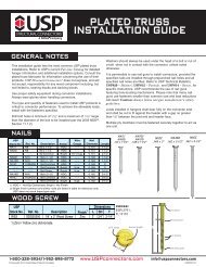
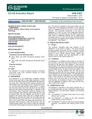
Joining 2 Ply 4x2 Floor Trusses<br />
The following information pertains to the use of the <strong>USP</strong>’s WS6 Wood Screws to fasten together a two-ply 4x2 floor truss<br />
girder, such that the induced loads are supported by both truss plies. Screw spacing and the location of each specific<br />
screw may vary depending on the design criteria for each application, and therefore must be determined by the truss or<br />
building designer. However, in the determination of screw locations, the following criterion shall also be considered.<br />
These criterion are varying dependent upon how trusses are loaded as follows:<br />
Uniform/Distributed Load<br />
• Screws shall be installed into the top chord with a horizontal<br />
spacing between screws of not less than 4-inches on centre and<br />
not more than 24-inches on centre.<br />
• A minimum end distance of 4-inches must be maintained. If<br />
necessary, additional screws may be installed in the bottom chord.<br />
• Centre screw vertically on 11/2˝ dimension of top chord. If<br />
splitting occurs, it may be necessary to pre-drill the holes in<br />
accordance with the code.<br />
• The screws shall be installed with the headed end of the screw<br />
on the loaded truss. If either ply is “the loaded truss”, the screws<br />
shall be divided between the two plies, with the spacing on each<br />
side twice the minimum indicated above.<br />
• The screws shall not be installed through the metal truss plates,<br />
unless approved by the truss designer and the plates are<br />
pre-drilled, on each side to a 1/4-inch diameter. Do not drill through<br />
the wood.<br />
• The maximum gap between the wood members of the two<br />
trusses shall be 1/8-inch.<br />
• The truss designer shall design the truss members with the<br />
capacity and capability of the screws in mind, and shall meet all<br />
provisions of the code and ANSI/TPI.<br />
• Individual screw locations may need to be adjusted to avoid<br />
conflicts with connectors, problematic wood or other framing<br />
members. Adjustments should follow the criteria described in this<br />
section.<br />
Concentrated/Point Load<br />
The placement of fasteners for concentrated loading includes all<br />
requirements of uniform loading with the additional following<br />
criteria:<br />
• Loads must occur over a vertical member, and the necessary<br />
concentration of screws shall be installed in the vertical member.<br />
• Additional screws may be installed on the top chord and<br />
adjacent web members if necessary.<br />
• The fasteners should be grouped as close to the concentrated<br />
load as possible, but satisfy the same minimum spacing<br />
indicated for uniform loading.<br />
• In no case shall the required group of fasteners extend beyond<br />
12-inches from the location of the concentrated load.<br />
Uniform/Distributed Load<br />
Applied distributed load<br />
WS6 Wood Screws<br />
WS6 Wood Screw<br />
Additional<br />
WS6 Wood Screw<br />
if necessary<br />
Concentrated/Point Load<br />
12˝<br />
max<br />
Applied Concentrated Load<br />
Applied Concentrated Load<br />
12˝<br />
max<br />
Fasteners<br />
Truss Members<br />
3 1 /2˝<br />
3 1 /2˝ 5/8˝ - 7 /8˝<br />
Factored Shear Loads (100%) 1<br />
<strong>USP</strong><br />
DF-L<br />
S-P-F<br />
Stock No. Ref. No. Lbs kN Lbs kN<br />
WS6 SDS25600 672 2.99 591 2.63<br />
1) Factored Resistance values determined in accordance<br />
with CSA O86-09 Clause 10.11.<br />
New products or updated product information are<br />
designated in red font.<br />
1 1 /2˝<br />
Screw Detail<br />
Typ. @ all<br />
members<br />
WS6 Wood Screw<br />
1-800-328-5934 • www.<strong>USP</strong>connectors.com 19<br />
<strong>USP</strong>2240-131