Installation Notes - USP Connectors
Installation Notes - USP Connectors
Installation Notes - USP Connectors

Create successful ePaper yourself
Turn your PDF publications into a flip-book with our unique Google optimized e-Paper software.
Holdowns – TD & TDX series continued<br />
© Copyright 2013 <strong>USP</strong> Structural <strong>Connectors</strong> ®<br />
<strong>USP</strong><br />
Stock No. 11<br />
TD5<br />
TD7<br />
TD9<br />
TD12<br />
TD15<br />
TDX2-TZ<br />
TDX5<br />
TDX6<br />
TDX8<br />
TDX10<br />
TDX14<br />
Dimensions (in) Fastener Schedule 4 Factored Resistance (115%) 1,2<br />
Bolts<br />
Min.<br />
Length of Bolt in Vertical Member<br />
Required<br />
1-1/2"<br />
3"<br />
3-1/2" 4-1/2" 5-1/2"<br />
Anchor<br />
Bolt End<br />
Steel<br />
Bolt<br />
Distance 5 Wood<br />
Ref. No. Gauge W H D CL Dia. Qty Dia. (in) Species Lbs kN Lbs kN Lbs kN Lbs kN Lbs kN<br />
-- --<br />
-- --<br />
-- --<br />
HD12<br />
-- --<br />
HD3B<br />
-- --<br />
HD5B<br />
HD8A<br />
HD7B<br />
HD9B<br />
7<br />
3<br />
3<br />
3<br />
3<br />
12<br />
10<br />
7<br />
7<br />
7<br />
3<br />
3<br />
3-3/8<br />
3-3/8<br />
3-1/2<br />
3-1/2<br />
2-1/16<br />
2-1/2<br />
3-1/2<br />
3-1/2<br />
3-1/2<br />
3-1/2<br />
6-3/8<br />
11-7/8<br />
16-1/2<br />
20-1/2<br />
25<br />
8-1/8<br />
9-3/8<br />
11-1/8<br />
14-5/8<br />
18-1/8<br />
20-1/2<br />
3-3/4<br />
3-5/8<br />
4-1/4<br />
4-1/4<br />
4-3/8<br />
2-3/4<br />
3-7/8<br />
3-3/4<br />
3-3/4<br />
3-3/4<br />
3-5/8<br />
2-1/8<br />
2-1/8<br />
2-1/8<br />
2-1/8<br />
2-1/8<br />
1-1/2<br />
2<br />
2<br />
2<br />
2<br />
2-1/8<br />
3/4<br />
1-1/8<br />
1-1/8<br />
1-1/8<br />
1-1/4<br />
5/8<br />
3/4<br />
7/8<br />
7/8<br />
7/8<br />
1<br />
2<br />
3<br />
3<br />
4<br />
5<br />
2<br />
2<br />
2<br />
3<br />
4<br />
4<br />
3/4<br />
7/8<br />
1<br />
1<br />
1<br />
5/8<br />
3/4<br />
7/8<br />
7/8<br />
7/8<br />
1<br />
5-1/4<br />
6-1/8<br />
7<br />
7<br />
7<br />
4-1/2<br />
5-1/4<br />
6-1/8<br />
6-1/8<br />
6-1/8<br />
7<br />
DF-L<br />
DF-L<br />
DF-L<br />
DF-L<br />
DF-L<br />
DF-L<br />
DF-L<br />
DF-L<br />
DF-L<br />
DF-L<br />
DF-L<br />
1560<br />
2725<br />
-- --<br />
-- --<br />
-- --<br />
1300<br />
1560<br />
1815<br />
2725<br />
3635<br />
4150<br />
6.94<br />
12.12<br />
-- --<br />
-- --<br />
-- --<br />
5.78<br />
6.94<br />
8.07<br />
12.12<br />
16.17<br />
18.46<br />
3115<br />
5450<br />
6225<br />
8310<br />
10385<br />
2525<br />
3115<br />
3635<br />
5450<br />
7270<br />
8310<br />
13.86<br />
24.24<br />
27.69<br />
36.96<br />
46.19<br />
11.23<br />
13.86<br />
16.17<br />
24.24<br />
32.34<br />
36.96<br />
3635<br />
6360<br />
7270<br />
9690<br />
12110<br />
2525<br />
3635<br />
4240<br />
6360<br />
8480<br />
9690<br />
16.17<br />
28.29<br />
32.34<br />
43.10<br />
53.87<br />
11.23<br />
16.17<br />
18.86<br />
28.29<br />
37.72<br />
43.10<br />
-- --<br />
-- --<br />
9345<br />
12460<br />
15570<br />
-- --<br />
-- --<br />
-- --<br />
-- --<br />
-- --<br />
-- --<br />
-- --<br />
-- --<br />
41.57<br />
55.42<br />
69.26<br />
-- --<br />
-- --<br />
-- --<br />
-- --<br />
-- --<br />
-- --<br />
5710<br />
9995<br />
11420<br />
15225<br />
19035<br />
2525<br />
5695<br />
6665<br />
9995<br />
13325<br />
15225<br />
25.40<br />
44.46<br />
50.80<br />
67.72<br />
84.67<br />
11.23<br />
25.33<br />
29.65<br />
44.46<br />
59.27<br />
67.72<br />
S-P-F<br />
S-P-F<br />
S-P-F<br />
S-P-F<br />
S-P-F<br />
S-P-F<br />
S-P-F<br />
S-P-F<br />
S-P-F<br />
S-P-F<br />
S-P-F<br />
1230<br />
2150<br />
-- --<br />
-- --<br />
-- --<br />
1025<br />
1230<br />
1440<br />
2150<br />
2870<br />
3275<br />
5.47<br />
9.56<br />
-- --<br />
-- --<br />
-- --<br />
4.56<br />
5.47<br />
6.41<br />
9.56<br />
12.77<br />
14.57<br />
2460<br />
4300<br />
4915<br />
6555<br />
8195<br />
1795<br />
2460<br />
2870<br />
4300<br />
5740<br />
6555<br />
10.94<br />
19.13<br />
21.86<br />
29.16<br />
36.45<br />
7.98<br />
10.94<br />
12.77<br />
19.13<br />
25.53<br />
29.16<br />
2870<br />
5020<br />
5740<br />
7645<br />
9560<br />
1795<br />
2870<br />
3345<br />
5020<br />
6695<br />
7645<br />
12.77<br />
22.33<br />
25.53<br />
34.01<br />
42.52<br />
7.98<br />
12.77<br />
14.88<br />
22.33<br />
29.78<br />
34.01<br />
-- --<br />
-- --<br />
7375<br />
9835<br />
12295<br />
-- --<br />
-- --<br />
-- --<br />
-- --<br />
-- --<br />
-- --<br />
-- --<br />
-- --<br />
32.81<br />
43.75<br />
54.69<br />
-- --<br />
-- --<br />
-- --<br />
-- --<br />
-- --<br />
-- --<br />
4510<br />
7890<br />
9015<br />
12025<br />
15025<br />
1795<br />
4510<br />
5260<br />
7890<br />
10515<br />
12025<br />
20.06<br />
35.10<br />
40.10<br />
53.49<br />
66.83<br />
7.98<br />
20.06<br />
23.40<br />
35.10<br />
46.77<br />
53.49<br />
1) Factored resistances have been increased 15% for short-term loads such as wind and earthquake; reduce for other load durations in accordance with the code.<br />
2) The designer must specify stud or post to resist published load values.<br />
3) The designer must specify anchor bolt type, length, and embedment.<br />
4) All models may be installed with greater than the required anchor end distance with no chart load reduction.<br />
5) The designer shall consider the effect of compression, bearing, tension, and combined bending due to device eccentricity when applicable.<br />
6) Holdowns raised off of the sill plate may have higher deflection values.<br />
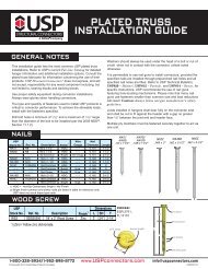
Holdowns<br />
Sources of Deflection at the Shearwall Holdown Connections<br />
The following are some of the sources of deflection that should be<br />
evaluated by the designer. See the illustration, which applies to other<br />
holdown configurations.<br />
A. Improperly-sized stud/post bolt holes – increased bolt slip can occur if<br />
stud/post bolt holes are oversized and exceed the NDS ® recommended bolt<br />
hole diameter.<br />
B<br />
C<br />
A<br />
Shearwall<br />
End Post<br />
Bearing<br />
Plates<br />
B. Stud/Post bolt holes – bolt slip can occur.<br />
C. Wood crushing at stud/post bolt hole perimeters –<br />
the use of larger washers/bearing plates can reduce stress-induced wood<br />
crushing at bolt bearing locations.<br />
D. Eccentricity in stud/post caused by holdown –<br />
holdowns installed on only one side of a stud or post result in an eccentricity<br />
which causes increased stresses and movement in a shearwall system.<br />
E. Nut spin – anchor bolt nuts that are not restrained can spin loose during<br />
cyclic loading, allowing movement; the use of steel nylon locking nuts or<br />
thread adhesive may prevent nut spin.<br />
F. Loose nuts – increased movement can occur when nuts are not<br />
sufficiently tightened.<br />
G. Holdown deflection – holdown deflection can occur when the shearwall<br />
system is subjected to cyclic stress from earthquakes or high wind.<br />
H. Wood Shrinkage – due to drying, wood may shrink and cause bolted<br />
connections to become loose; periodic retightening may be required.<br />
I. Localized crushing at wood-bearing surfaces –<br />
excessive crushing at wood-bearing surfaces may result from compressive<br />
forces due to overturning during high wind or earthquake loading.<br />
H<br />
E<br />
G<br />
D<br />
F<br />
Holdown<br />
I<br />
Wood<br />
Sill Plate<br />
Holdown<br />
Anchor Bolt<br />
1 ⁄4˝ x 3˝ x 3˝<br />
Steel Plate<br />
Foundation<br />
Concrete<br />
1-800-328-5934 • www.<strong>USP</strong>connectors.com<br />
43<br />
<strong>USP</strong>2240-131