Installation Notes - USP Connectors
Installation Notes - USP Connectors
Installation Notes - USP Connectors

You also want an ePaper? Increase the reach of your titles
YUMPU automatically turns print PDFs into web optimized ePapers that Google loves.
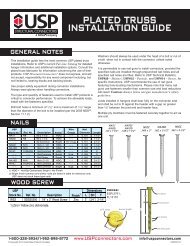
Scissor Truss Clips – STC series<br />
© Copyright 2013 <strong>USP</strong> Structural <strong>Connectors</strong> ®<br />
The STC provides uplift resistance by securing trusses to top plates.<br />
Slotted nail holes allow for horizontal movement as scissor trusses<br />
deflect.<br />
Materials: 12 gauge<br />
Finish: G90 galvanizing<br />
Codes: Load values are derived from data submitted to<br />
various North American building code evaluators.<br />
Fastener Schedule 2,3 Dimensions (in)<br />
Factored Resistance (115%) 1<br />
<strong>USP</strong><br />
Steel<br />
Truss<br />
Plate DF-L (Lbs) DF-L (kN) S-P-F (Lbs) S-P-F (kN)<br />
Stock No. Ref. No. Gauge Description W1 W2 Qty Type Qty Type F1 Uplift F1 Uplift F1 Uplift F1 Uplift<br />
STC24 TC24 12 2 x 4 top plate 3-9/16 1-5/8 5 10d x 1-1/2 6 10d x 1-1/2 550 1525 2.45 6.78 390 1085 1.73 4.83<br />
STC26 TC26 12 2 x 6 top plate 5-1/2 1-5/8 5 10d x 1-1/2 6 10d x 1-1/2 550 1525 2.45 6.78 390 1085 1.73 4.83<br />
STC28 TC28 12 2 x 8 top plate 7-1/4 1-5/8 5 10d x 1-1/2 6 10d x 1-1/2 550 1525 2.45 6.78 390 1085 1.73 4.83<br />
1) Factored resistances have been increased 15% for short-term loads such as wind and earthquake; reduce for other load durations in accordance with the code.<br />
2) Minimum nail embedment shall be 8 nail diameters (typ).<br />
3) NAILS: <br />
FLOOR TRUSS CLIPS – FTC SERIES<br />
The FTC slides easily onto the top or bottom chord and provides a guide to<br />
help position and support the second truss during assembly.<br />
Materials:<br />
Finish:<br />
Codes:<br />
18 gauge<br />
G90 galvanizing<br />
Factored resistances are derived from data submitted<br />
to various North American building code evaluators<br />
and are in accordance with CSA O86-09.<br />
<strong>Installation</strong>:<br />
• Use all specified fasteners. See Product <strong>Notes</strong>, page 10.<br />
• The truss designer must determine the number of clips required<br />
and the spacing between clips based on loading conditions.<br />
Concentrated Load condition (side-loaded onto a 2-ply truss):<br />
• The FTC clips shall be installed in pairs, or multiples of two, on<br />
either side of, and within 12" of a concentrated load.<br />
4 3 /8˝<br />
• Divide half of the concentrated load by the clip capacity to<br />
determine the number of clips required.<br />
Example:<br />
Concentrated load = 3000 lbs. FTC1 capacity (DF-L) = 1245 lbs<br />
1<br />
⁄2 (3000 lbs)<br />
= 1.2 = 2 clips<br />
1245 lbs<br />
Install two FTC1 clips, one on each side of, and within 12" of the<br />
concentrated load.<br />
Uniform Load condition (side-loaded onto a 2-ply truss):<br />
• To transfer uniform loads to the second ply, the FTC clips shall be<br />
installed at a regular interval along the loaded chord. Spacing<br />
between clips is limited to 24" maximum.<br />
• Divide the clip capacity by half of the required load per lineal foot<br />
(PLF) to determine the spacing between clips.<br />
Example:<br />
Uniformly distributed load = 500 PLF. FTC1 capacity (DF-L) = 1245 lbs<br />
1245 lbs<br />
1<br />
= 4.98' spacing<br />
⁄2 (500 PLF)<br />
Space clips at 24" (MAX) along the loaded chord.<br />
4 3 /8˝<br />
W 1<br />
H<br />
2˝ 1 1 /8˝<br />
FTC<br />
6 1 /16˝<br />
W 2<br />
3 1 /16˝<br />
2 1 /16˝<br />
F 1<br />
Typical STC<br />
installation<br />
<strong>Installation</strong>:<br />
• Use all specified fasteners.<br />
See Product <strong>Notes</strong>, page 10.<br />
• When installing, do not fully set<br />
nails.<br />
• Locate nails into the center of<br />
slots to allow for horizontal<br />
movement.<br />
Step 1 Step 2<br />
Typical FTC2F retrofit installation<br />
Dimensions (in) Fastener Schedule 2,4 Factored Maximum Transfer Resistance 1,3<br />
Truss <strong>USP</strong><br />
Steel<br />
DF-L (Lbs) DF-L (kN) S-P-F (Lbs) S-P-F (kN)<br />
7 5/8˝<br />
Size Stock No. Ref. No. Gauge W1 W2 H Qty Type 100% 100% 100% 100%<br />
4<br />
3 x 2 FTC32 -- -- 18 2-1/2 2-1/16 1-1/2 10 10d x 1-1/2 980 4.36 850 3.78<br />
3/8˝<br />
FTC1 -- -- 18 3-1/2 3-1/16 1-1/2 10 10d x 1-1/2 1245 5.54 1080 4.80<br />
4 x 2<br />
2 1/16˝<br />
FTC1F -- -- 18 3-1/16 -- -- 4-3/8 10 10d x 1-1/2 1245 5.54 1080 4.80<br />
FTC2 -- -- 18 3-1/2 3-1/16 3 10 10d 1245 5.54 1080 4.80<br />
(2) 4 x 2<br />
FTC2F -- -- 18 3-1/16 -- -- 4-3/8 10 10d 1245 5.54 1080 4.80<br />
3 1/16˝<br />
1) Factored transfer resistances are for 100% floor load, and shall not be increased for short term load duration.<br />
2) Minimum nail embedment shall be 8 nail diameters (typ).<br />
FTC2F<br />
3) Truss designer shall determine the number of clips for concentrated loads and the spacing for uniform loads.<br />
4) NAILS:<br />
New products or updated product information are designated in red font.<br />
1-800-328-5934 • www.<strong>USP</strong>connectors.com 177<br />
<strong>USP</strong>2240-131<br />
W 2<br />
W 1<br />
1 1/4˝ slots<br />
STC<br />
FTC1F<br />
Typical FTC<br />
installation<br />
Typical FTC<br />
2 ply metal web<br />
truss installation<br />
Plated Truss