User Manual - Ajckids.com
User Manual - Ajckids.com
User Manual - Ajckids.com

Create successful ePaper yourself
Turn your PDF publications into a flip-book with our unique Google optimized e-Paper software.
Wiring details<br />
8. Wiring details<br />
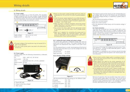
8.1. Power supply<br />
ECoS gets its power via a 2.1mm DC-socket. The secondary<br />
voltage corresponds with the track voltage; voltage stabilising<br />
or adjustments take place within the power supply, not within<br />
the <strong>com</strong>mand station. ECoS has its own internal protective circuitry<br />
for under-voltage and overload (-current).<br />
Supply voltage: 14V to 22V AC or DC<br />
Supply current: max. 5A<br />
• The peak voltage of the transformer may not exceed 22V in<br />
open circuit operation.<br />
• The use of other power packs may lead to the destruction<br />
of the ECoS.<br />
8.2. Power supply<br />
A power supply with the following characteristics is delivered<br />
with ECoS:<br />
VIn: 100V – 240 V AC, 50 / 60 Hz<br />
Input current: 1.8A max.<br />
VOut: adjustable from 15V - 21V DC, stabilised<br />
Output current: 5A max.<br />
Plug: DC plug, 2.1mm, 1.8m flying lead<br />
c)<br />
�<br />
Outside: „-“<br />
a) Power-LED (red)<br />
b) Output socket (low voltage)<br />
c) Main socket<br />
Inside: „+“<br />
Figure 11<br />
Figure 12<br />
a)<br />
b)<br />
• Please use the power supply provided with ECoS solely for<br />
powering ECoS. Do not use it for other household appliances.<br />
• Check the power supply regularly for any visible damage of<br />
the housing or the mains cable. Damaged parts may never<br />
be used! Do not attempt to repair the power supply! Extreme<br />
danger – risk of fatal injury!<br />
• Make sure there is sufficient ventilation around the power<br />
supply. Mounting in furniture without air circulation may<br />
lead to overheating of even fire!<br />
• First connect the mains cable with the appropriate socket<br />
of the power pack and then plug it into a suitable power<br />
outlet.<br />
• Never use V adapters for connecting the power pack to<br />
other devices besides the <strong>com</strong>mand station! This could<br />
cause an inadmissible contact to ground that could lead to<br />
the destruction of your <strong>com</strong>mand station!<br />
8.2.1. Setting the input voltage and output voltage<br />
The power pack generates a stabilised voltage that serves to<br />
power your model train layout. The output voltage must be<br />
adjusted to the appropriate value subject to the scale of your<br />
trains.<br />
For this purpose there is a small, round opening at the front of<br />
the power pack that allows you to set the voltage with the aid<br />
of a screw driver:<br />
Left hand limit: ca. 14.5V<br />
Right hand limit: ca. 21.5V<br />
8.2.2. Practical voltage settings<br />
Figure 13<br />
14V 21V<br />
We re<strong>com</strong>mend the following settings for the different scales:<br />
• N gauge: 15V - 16V<br />
• H0 DC (DCC): 16V - 18V<br />
• H0 three-rail-system: 18V - 20V<br />
• 1 gauge: 18V - 21V<br />
• G gauge: 20V - 21V<br />
The integral current monitor shows you the corresponding output<br />
voltage. With the aid of this monitor you can determine<br />
the desired voltage precisely. It is explained in greater detail in<br />
chapter 23.<br />
We re<strong>com</strong>mend proceeding as follows:<br />
• Start your <strong>com</strong>mand station<br />
• Open the current monitor<br />
• Turn the adjustment wheel slowly until the desired voltage is<br />
displayed.<br />
8.3. Track connection<br />
The tracks are connected via a two-way socket with a removable<br />
plug. Please make sure you us cables of adequate size<br />
for your track power. We re<strong>com</strong>mend wires of at least 1.5mm²<br />
(better: 2.5mm²) cross section. In larger layouts connect track<br />
power every two meters to the tracks.<br />
�<br />
Figure 14<br />
ECoS uses an H4-bridge (full bridge) for the track power. Therefore<br />
with ECoS – contrary to older Märklin® systems - there is<br />
no „Common” (Ground).<br />
Nevertheless it is advisable to use a <strong>com</strong>mon ground (normally<br />
the rails) in existing three-rail-systems with several power districts<br />
(boosters).<br />
• Never connect another digital system or analogue transformer<br />
to the same circuit as ECoS. Your ECoS may be damaged<br />
or destroyed!<br />
• Please observe the need for the correct separation of all<br />
power districts should your layout be divided in several such<br />
districts. As normal practice the centre-rail will be isolated.<br />
The outer rails may form the <strong>com</strong>mon ground provided<br />
each booster has its own power supply (transformer).<br />
• ECoS supplies up to 4A track current. Always consider if you<br />
actually need such a high output current. In case of a short<br />
circuit your locos may be damaged and there may be risk of<br />
fire! Reduce the maximum current to a sensible level. Also<br />
refer to chapter 21.1.3.<br />
Remove all capacitors that may possibly haven been wired to<br />
the track power supply cable in your layout. They would cause<br />
a strong heat build-up of ECoS and impair the power output.<br />
Almost in every connecting track in an analogue starter kit<br />
(Roco®, Märklin®) are resp. were capacitors installed.<br />
11