User Manual - Ajckids.com
User Manual - Ajckids.com
User Manual - Ajckids.com

You also want an ePaper? Increase the reach of your titles
YUMPU automatically turns print PDFs into web optimized ePapers that Google loves.
14<br />
Wiring details<br />
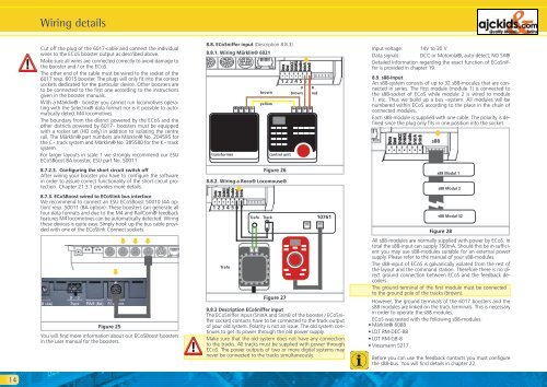
Cut off the plug of the 6017-cable and connect the individual<br />
wires to the ECoS booster output as described above.<br />
Make sure all wires are connected correctly to avoid damage to<br />
the booster and / or the ECoS.<br />
The other end of the cable must be wired to the socket of the<br />
6017 resp. 6015 booster. The plugs will only fit into the correct<br />
sockets dedicated for the particular device. Other boosters are<br />
to be connected to the first one according to the instructions<br />
given in the booster manuals.<br />
With a Märklin® - booster you cannot run lo<strong>com</strong>otives operating<br />
with the Selectrix® data format nor is it possible to automatically<br />
detect M4 lo<strong>com</strong>otives.<br />
The boundary from the district powered by the ECoS and the<br />
other districts powered by 6017 - boosters must be equipped<br />
with a rocker set (HO only) in addition to isolating the centre<br />
rail. The Märklin® part numbers are Märklin® No. 204595 for<br />
the C - track system and Märklin® No. 385580 for the K - track<br />
system.<br />
For larger layouts in scale 1 we strongly re<strong>com</strong>mend our ESU<br />
ECoSBoost 8A booster, ESU part No. 50011.<br />
8.7.2.3. Configuring the short circuit switch off<br />
After wiring your booster you have to configure the software<br />
in order to assure correct functionality of the short circuit protection.<br />
Chapter 21.3.1 provides more details.<br />
8.7.3. ECoSBoost wired to ECoSlink bus interface<br />
We re<strong>com</strong>mend to connect an ESU ECoSBoost 50010 (4A option)<br />
resp. 50011 (8A option): These boosters can generate all<br />
four data formats and due to the M4 and RailCom® feedback<br />
features M4 lo<strong>com</strong>otives can be automatically detected. Wiring<br />
these devices is quite easy. Simply hook up the bus cable provided<br />
with one of the ECoSlink Connect sockets.<br />
�<br />
Figure 25<br />
�<br />
�<br />
�<br />
You will find more information about our ECoSBoost boosters<br />
in the user manual for the boosters.<br />
8.8. ECoSniffer input (Description 8.8.3)<br />
8.8.1. Wiring Märklin® 6021<br />
brown<br />
yellow<br />
transformer control unit<br />
Figure 26<br />
8.8.2. Wiring a Roco® Lo<strong>com</strong>ouse®<br />
�<br />
1 2 3 4 5 6 7<br />
Trafo<br />
Figure 27<br />
0<br />
brown<br />
�<br />
1 2 3 4 5 6 7<br />
B<br />
red<br />
Trafo Track<br />
10761<br />
8.8.3 Description ECoSniffer input<br />
The ECoSniffer input (SnInA and SnInB of the booster / ECoSniffer<br />
socket) contacts have to be connected to the track output<br />
of your old system. Polarity is not an issue. The old system continues<br />
to get its power through the old power supply.<br />
Make sure that the old system does not have any connection<br />
to the tracks. All tracks must be supplied with power through<br />
ECoS. The power outputs of two or more digital systems may<br />
never be connected to the tracks simultaneously.<br />
Input voltage: 14V to 30 V<br />
Data signals: DCC or Motorola®, auto-detect; NO SX®<br />
Detailed information regarding the exact function of ECoSniffer<br />
is provided in chapter 19.<br />
8.9. s88-Input<br />
An s88-system consists of up to 32 s88-mocules that are connected<br />
in series. The first module (module 1) is connected to<br />
the s88-socket of ECoS while module 2 is wired to module<br />
1, etc. Thus we build up a bus –system. All modules will be<br />
numbered within ECoS according to the place in the chain of<br />
connected modules.<br />
Each s88-module is supplied with one cable. The polarity is defined<br />
since the plug only fits in one position into the socket.<br />
�<br />
s88<br />
s88 Modul 1<br />
s88 Modul 2<br />
s88 Modul 32<br />
Figure 28<br />
All s88-modules are normally supplied with power by ECoS. In<br />
total the s88-input can supply 750mA. Should this be in sufficient<br />
you may use s88-modules suitable for an external power<br />
supply. Please refer to the manual of your s88-modules.<br />
The s88-input of ECoS is galvanically isolated from the rest of<br />
the layout and the <strong>com</strong>mand station. Therefore there is no direct<br />
ground connection between ECoS and the feedback decoders.<br />
The ground terminal of the first module must be connected<br />
to the ground pole of the tracks (brown).<br />
However, the ground terminals of the 6017 boosters and the<br />
s88 modules are linked on the track terminals. This is necessary<br />
in order to operate the s88 modules.<br />
ECoS was tested with the following s88-modules:<br />
• Märklin® 6088<br />
• LDT RM-DEC-88<br />
• LDT RM-GB-8<br />
• Viessmann 5217<br />
Before you can use the feedback contacts you must configure<br />
the s88-bus. You will find details in chapter 22.