User Manual - Ajckids.com
User Manual - Ajckids.com
User Manual - Ajckids.com

You also want an ePaper? Increase the reach of your titles
YUMPU automatically turns print PDFs into web optimized ePapers that Google loves.
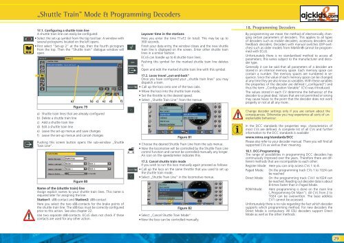
17.1. Configuring a shuttle train line<br />
A shuttle train line can easily be configured:<br />
• Select the set-up symbol from the top tool bar. A window with<br />
several pictograms located on the left opens.<br />
• First select “Set-up 2“ at the top, then the fourth pictogram<br />
from the top. Then the “Shuttle train” dialogue window will<br />
open.<br />
�<br />
„Shuttle Train” Mode & Programming Decoders<br />
a) b) c) e)<br />
Figure 79<br />
a) Shuttle train lines that are already configured<br />
b) Delete a shuttle train line<br />
c) Add a shuttle train line<br />
d) Edit a shuttle train line<br />
e) Leave the set-up menue and save changes<br />
f) Leave the set-up menue and cancel changes<br />
d) f)<br />
Pushing this screen button opens the sub-window „Shuttle<br />
Train Line“.<br />
Figure 80<br />
Name of the (shuttle train) line<br />
Assign explicit names to your shuttle train lines. This name is<br />
required later for assigning the line.<br />
Station1: s88-contact and Station2: s88-contact<br />
Here you select the two s88-contacts for the brake points of<br />
the shuttle train line. The s88-bus must be correctly configured<br />
prior to this action. See also chapter 22.<br />
Use two separate s88-contacts. ECoS does not check if these<br />
contacts are used for any other action.<br />
Layover time in the stations<br />
Here you enter the time T1+T2 (in total). This may be up to<br />
300 seconds.<br />
Finish your data entry, the window closes and the new shuttle<br />
train line is displayed on the screen. Enter other shuttle train<br />
lines in a similar fashion.<br />
ECoS can handle up to 8 shuttle train lines.<br />
Pushing this symbol for the marked shuttle train line deletes<br />
it.<br />
Open and edit the marked shuttle train line with this symbol.<br />
17.2. Locos travel „out-and-back”<br />
Once you have configured your „shuttle train lines” you may<br />
dispatch a train.<br />
• Call up the loco onto one of the two cabs.<br />
• Move the loco into the shuttle train mode.<br />
• Set the throttle to the desired speed.<br />
• Select „Shuttle Train Line” from the menue.<br />
Figure 81<br />
• Choose the desired Shuttle Train Line from the sub menue.<br />
• Now the lo<strong>com</strong>otive will be controlled by the Shuttle Train Line<br />
control function and cannot be controlled manually any longer.<br />
An icon on the speedometer indicates this.<br />
17.3. Cancel shuttle train mode<br />
If you wish to run this loco manually again proceed as follows:<br />
• Call up the loco on the same throttle that you used to set up<br />
the shuttle train mode.<br />
• Select „Shuttle Train Line” in the lo<strong>com</strong>otive menue.<br />
Figure 82<br />
• Select „Cancel Shuttle Train Mode”<br />
• Now the loco can be controlled manually.<br />
18. Programming Decoders<br />
By programming we mean the method of electronically changing<br />
certain parameters of decoders. This applies to all types<br />
of decoders such as mobile decoders, accessory decoders and<br />
feedback decoders. Decoders with manual switches (DIP-switches)<br />
such as older models from Märklin® cannot be programmed<br />
with ECoS.<br />
Unfortunately there is no standardised method to access all<br />
parameters; this varies subject to the manufacturer and decoder<br />
type.<br />
Generally it can be said that all parameters of a decoder are<br />
stored in an internal memory space. Each memory space can<br />
contain a number. The memory spaces are numbered in sequence.<br />
Since the value of each memory space can be changed<br />
at any time they are also know as variables. With these variables<br />
the properties of the decoder are defined („configured”) and<br />
thus the term „Configuration Variable” (CV) was introduced.<br />
The values stored in each CV determine the behaviour of the<br />
decoder to a great deal. Values that are not permitted or wrong<br />
may cause havoc to the point that the decoder does not work<br />
properly or not at all any more.<br />
Change decoder settings only if you are certain about the<br />
consequences. Otherwise you may experience all sorts of unexplainable<br />
behaviour.<br />
In the DCC standards the properties resp. characteristics of<br />
most CVs are defined. A <strong>com</strong>plete list of all CVs and further<br />
information to the DCC standards is available<br />
www.nmra.org/standards/DCC<br />
Please also refer to your decoder manual. There you will find all<br />
supported CVs as well as their meaning.<br />
18.1. DCC-Programming<br />
The range of possibilities in programming DCC decoders has<br />
continuously improved over the years. Therefore there are different<br />
methods that are in<strong>com</strong>patible to each other:<br />
Register Mode: Here you can only access CVs 1 to 8.<br />
Paged Mode: On the programming track CVs 1 to 1024 can<br />
be reached<br />
Direct Mode: On the programming track CVs1 to1024 can<br />
be reached. Reading out decoder data is about<br />
8-times faster than in Paged Mode.<br />
POM Mode: Here programming is done on the main line<br />
(„Programming On Main“). All CVs from 2 to<br />
1024 can be overwritten. The base address<br />
CV1 cannot be accessed.<br />
Unfortunately there is no rule regarding the fact which decoder<br />
supports which programming method. For new decoders the<br />
Direct Mode is <strong>com</strong>pulsory. All ESU decoders support Direct<br />
Mode as well as the other methods.<br />
29