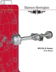
workshop manual rear axles rf17n/h r17n/h - Marmon-Herrington
workshop manual rear axles rf17n/h r17n/h - Marmon-Herrington
workshop manual rear axles rf17n/h r17n/h - Marmon-Herrington

Create successful ePaper yourself
Turn your PDF publications into a flip-book with our unique Google optimized e-Paper software.
Amennyiben ett�l eltérés mutatkozik, azt távtartó<br />
gy�r� cserével korrigáljuk. Ha nagyobb a legördülés<br />
értéke az el�írtnál, úgy magasabb, ha kisebb, úgy<br />
alacsonyabb távtartó gy�r� párt alkalmazzunk.<br />
Amennyiben a beállítás megfelel�, úgy ezután lehet a<br />
beállító készülékr�l az alkatrészeket a meghajtó<br />
kúpkerékre REINSTALLING átszerelni. THE DRIVE Ügyeljünk PINION arra, hogy a<br />
meghajtó By means kúpkerékre of the tools az shown el�z� beállításnál drive the cone alkalmazott of the<br />
alkatrészek inner taper kerüljenek roller bearing felszerelésre! (12) onto the drive pinion<br />
(Fig. 7.).<br />
A MEGHAJTÓ KÚPKERÉK FELSZERELÉSE<br />
A bels� kúpgörg�s csapágy (12) bels� részét üsük fel<br />
az ábrázolt szerszámokkal a meghajtó kúpkerékre<br />
(7. Position ábra). the distance sleeve (11), the previously selected<br />
distance ring (10), the differential carrier II. subassembled<br />
with bearing outer races, them by means<br />
By means of the tools shown drive the cone of the<br />
of drive sleeve 4518-00022-4 drive on the cone of<br />
inner taper roller bearing (12) onto the drive pinion<br />
outer taper roller bearing to bottom out, taking care of<br />
(Fig. 7.).<br />
proper connection of the taper roller bearings.<br />
Drive on the driven gear (50), position the washer,<br />
screw on the flanged castle nut (1) and secure by cotter<br />
(2).<br />
7. ábra: A BELS� KÚPGÖRG�S CSAPÁGY<br />
BELS� Position RÉSZÉNEK the drive pinion FELÜTÉSE subassembled in this way to<br />
Fig: stand 7.: of DRIVING the adjusting ON THE device INNER Drw. No. TAPER 4970-00489,<br />
secure the driven gear by lock of the device as shown<br />
ROLLER BEARING CONE<br />
in Fig. 6. and tighten the flanged castle nut to 850 -<br />
1050 Nm torque.<br />
Helyezzük fel a távtartó hüvelyt (11), az el�z�ek<br />
szerint a kiválasztott távtartó gy�r�t (10), a csapágy<br />
küls� gy�r�kkel el�szerelt hajtóm�ház II.-t, majd a<br />
küls� kúpgörg�s csapágy bels� részét üssük fel a<br />
4518-00022-4 rajzszámú nyomó hüvellyel ütközésig, a<br />
kúpgörg�s csatlakozásra ügyelve.<br />
Check the rolling torque as described earlier. If<br />
Üssük deviation fel is a experienced hajtott fogaskereket repeat the (50), adjustment tegyük until fel az<br />
alátétet, obtaining hajtsuk the specified fel a peremes value. koronás anyát (1) és<br />
sasszeggel (2) biztosítsuk.<br />
Tegyük fel az így el�szerelt meghajtó kúpkereket a<br />
4970-00489 rajzszámú beállító készülék állványára,<br />
rögzítsük a hajtott fogaskereket a készülék<br />
reteszel�jével a 6. ábra szerint, és húzzuk meg a<br />
peremes koronás anyát 850 - 1050 Nm nyomatékkal.<br />
Ellen�rizzük le a legördülési nyomatékot az el�z�ek<br />
szerint. Amennyiben eltérést észlelünk a beállítást<br />
64<br />
megismételjük addig, amíg az el�írtaknak megfelel.<br />
.<br />
290<br />
In case of deviation from this value perform correction<br />
by changing the distance ring. If the rolling torque is<br />
higher than specified use higher distance ring pair,<br />
while at lower torque use lower one.<br />
4518-00022-2, -3<br />
When the adjustment is proper relocate the parts from<br />
the adjusting device to the drive pinion. Make sure to<br />
install only the parts used for adjustment over to the<br />
drive pinion.<br />
REINSTALLING THE DRIVE PINION<br />
583.10-40<br />
Position the distance sleeve (11), the previously<br />
selected distance ring (10), the differential carrier II.<br />
subassembled with bearing outer races, them by means<br />
of drive sleeve 4518-00022-4 drive on the cone of<br />
outer taper roller bearing to bottom out, taking care of<br />
proper connection of the taper roller bearings.<br />
Fig. 7.: DRIVING ON THE INNER TAPER ROLLER<br />
BEARING CONE<br />
Drive on the driven gear (50), position the washer,<br />
screw on the flanged castle nut (1) and secure by<br />
cotter (2).<br />
Position the drive pinion subassembled in this way to<br />
stand of the adjusting device Drw. No. 4970-00489,<br />
secure the driven gear by lock of the device as shown<br />
in Fig. 6. and tighten the flanged castle nut to 850 -<br />
1050 Nm torque.<br />
Check the rolling torque as described earlier. If<br />
deviation is experienced repeat the adjustment until<br />
obtaining the specified value.<br />
.<br />
93