AS9N010B.STB AS-93plus Service Manual.fm - LIQUID-scan GmbH ...
AS9N010B.STB AS-93plus Service Manual.fm - LIQUID-scan GmbH ...
AS9N010B.STB AS-93plus Service Manual.fm - LIQUID-scan GmbH ...

You also want an ePaper? Increase the reach of your titles
YUMPU automatically turns print PDFs into web optimized ePapers that Google loves.
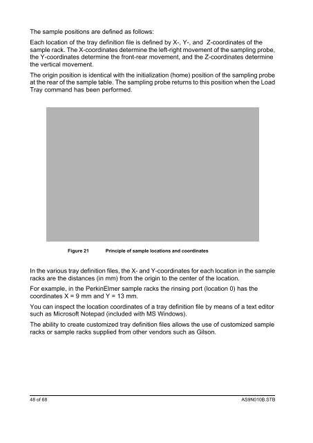
The sample positions are defined as follows:<br />
Each location of the tray definition file is defined by X-, Y-, and Z-coordinates of the<br />
sample rack. The X-coordinates determine the left-right movement of the sampling probe,<br />
the Y-coordinates determine the front-rear movement, and the Z-coordinates determine<br />
the vertical movement.<br />
The origin position is identical with the initialization (home) position of the sampling probe<br />
at the rear of the sample table. The sampling probe returns to this position when the Load<br />
Tray command has been performed.<br />
Figure 21 Principle of sample locations and coordinates<br />
In the various tray definition files, the X- and Y-coordinates for each location in the sample<br />
racks are the distances (in mm) from the origin to the center of the location.<br />
For example, in the PerkinElmer sample racks the rinsing port (location 0) has the<br />
coordinates X = 9 mm and Y = 13 mm.<br />
You can inspect the location coordinates of a tray definition file by means of a text editor<br />
such as Microsoft Notepad (included with MS Windows).<br />
The ability to create customized tray definition files allows the use of customized sample<br />
racks or sample racks supplied from other vendors such as Gilson.<br />
48 of 68 <strong><strong>AS</strong>9N010B</strong>.<strong>STB</strong>