AS9N010B.STB AS-93plus Service Manual.fm - LIQUID-scan GmbH ...
AS9N010B.STB AS-93plus Service Manual.fm - LIQUID-scan GmbH ...
AS9N010B.STB AS-93plus Service Manual.fm - LIQUID-scan GmbH ...

You also want an ePaper? Increase the reach of your titles
YUMPU automatically turns print PDFs into web optimized ePapers that Google loves.
1. Switch of the <strong>AS</strong>-93 by unplugging the power supply.<br />
2. Remove the sampling probe, the sample tubes and the sample racks<br />
from the sample tray table.<br />
3. With a knife carefully lift and remove the 4 caps that cover the<br />
mounting screws of the sample tray table.<br />
4. Remove the sample tray table and place it in front of the chassis.<br />
5. Loosen the 4 screws of the tower's bottom plate.<br />
6. Carefully turn the tower as much as the correction requires. Don't<br />
touch the arm during this procedure.<br />
7. To check the correction, mount the sample tray table and insert the left<br />
sample rack.<br />
8. Insert the sampling probe and move the sampling probe holder to<br />
location 0 and 5 by means of the Terminal program.<br />
9. Measure the X-offset with a millimeter scale. If there is still a different<br />
offset in X-direction repeat step 4 and 5.<br />
In general, a positional test can also preformed with the spectrometer<br />
operating software by means of the manual commands in the<br />
autosampler page.<br />
10.Check the X-offset also at the right side, i.e. position 146 and 157. If<br />
the X- offset on all corner locations is constant, a parallel misalignment<br />
is corrected.<br />
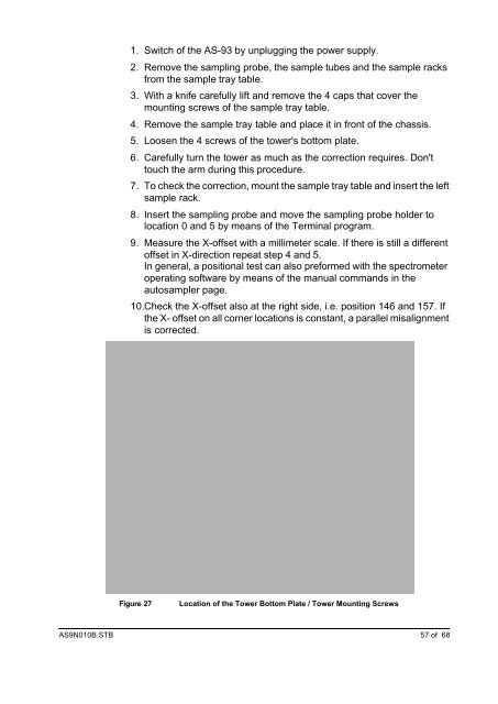
Figure 27 Location of the Tower Bottom Plate / Tower Mounting Screws<br />
<strong><strong>AS</strong>9N010B</strong>.<strong>STB</strong> 57 of 68