

Manual
Manual
Manual
- No tags were found...

You also want an ePaper? Increase the reach of your titles
YUMPU automatically turns print PDFs into web optimized ePapers that Google loves.
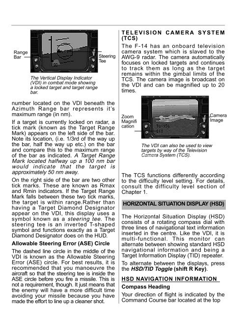
RangeBarThe Vertical Display Indicator(VDI) in combat mode showinga locked target and target rangebar.SteeringTeenumber located on the VDI beneath theAzimuth Range bar represents it’smaximum range (in nm).If a target is currently locked on radar, atick mark (known as the Target RangeMark) appears on the left side of the bar.Note its location, (i.e. 1/3rd of the way upthe bar, half the way up etc.) on the barand compare this to the maximum rangeof the bar as indicated. A Target RangeMark located halfway up a 100 nm barwould indicate that the target isapproximately 50 nm away.On the right side of the bar are two othertick marks. These are known as Rmaxand Rmin indicators. If the Target RangeMark falls between these two tick marks,the target is within range.Rather thanhaving a Target Diamond Designatorappear on the VDI, this display uses asymbol known as a steering tee. Thesteering tee is an inverted T-shapedsymbol and functions exactly as a TargetDiamond Designator does on the HUD.Allowable Steering Error (ASE) CircleThe dashed line circle in the middle of theVDI is known as the Allowable SteeringError (ASE) circle. For best results, it isrecommended that you manoeuvre theaircraft so that the steering tee is inside theASE circle before you fire a missile. This isnot a requirement, though. It just means thatthe enemy will have a more difficult timeavoiding your missile because you havemade the effort to line up a cleaner shot.TELEVISION CAMERA SYSTEM(TCS)The F-14 has an onboard televisioncamera system which is slaved to theAWG-9 radar. The camera automaticallyfocuses on locked targets and continuesto track them as long as the targetremains within the gimbal limits of theTCS. The camera image is broadcast onthe VDI and can be magnified up to 20times.ZoomMagnificationThe VDI can also be used to viewtargets by way of the TelevisionCamera System (TCS).CameraImageThe TCS functions differently accordingto the difficulty level setting. For details,consult the difficulty level section ofChapter 1.HORIZONTAL SITUATION DISPLAY (HSD)The Horizontal Situation Display (HSD)consists of a rotating compass dial withthree lines of navigational text informationinserted in the centre. Like the VDI, it ismulti-functional. This monitor canalternate between showing standard HSDnavigational information and being aTarget Information Display (TID) repeater.To alternate between the displays, pressthe HSD/TID Toggle (shift R Key).HSD NAVIGATION INFORMATIONCompass HeadingYour direction of flight is indicated by theCommand Course bar located at the top