AFS Foundry Sand Testing Equipment Operating Instructions Manual
AFS Foundry Sand Testing Equipment Operating Instructions Manual
AFS Foundry Sand Testing Equipment Operating Instructions Manual
- No tags were found...

Create successful ePaper yourself
Turn your PDF publications into a flip-book with our unique Google optimized e-Paper software.
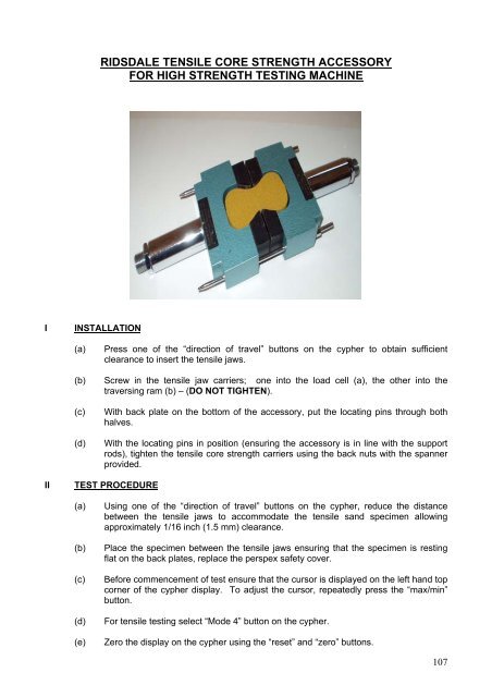
RIDSDALE TENSILE CORE STRENGTH ACCESSORYFOR HIGH STRENGTH TESTING MACHINEIINSTALLATION(a)(b)(c)(d)Press one of the “direction of travel” buttons on the cypher to obtain sufficientclearance to insert the tensile jaws.Screw in the tensile jaw carriers; one into the load cell (a), the other into thetraversing ram (b) – (DO NOT TIGHTEN).With back plate on the bottom of the accessory, put the locating pins through bothhalves.With the locating pins in position (ensuring the accessory is in line with the supportrods), tighten the tensile core strength carriers using the back nuts with the spannerprovided.IITEST PROCEDURE(a)(b)(c)(d)(e)Using one of the “direction of travel” buttons on the cypher, reduce the distancebetween the tensile jaws to accommodate the tensile sand specimen allowingapproximately 1/16 inch (1.5 mm) clearance.Place the specimen between the tensile jaws ensuring that the specimen is restingflat on the back plates, replace the perspex safety cover.Before commencement of test ensure that the cursor is displayed on the left hand topcorner of the cypher display. To adjust the cursor, repeatedly press the “max/min”button.For tensile testing select “Mode 4” button on the cypher.Zero the display on the cypher using the “reset” and “zero” buttons.107