AFS Foundry Sand Testing Equipment Operating Instructions Manual
AFS Foundry Sand Testing Equipment Operating Instructions Manual
AFS Foundry Sand Testing Equipment Operating Instructions Manual
- No tags were found...

You also want an ePaper? Increase the reach of your titles
YUMPU automatically turns print PDFs into web optimized ePapers that Google loves.
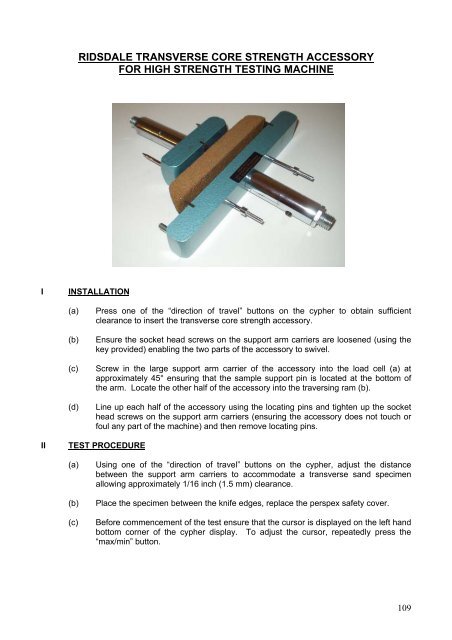
RIDSDALE TRANSVERSE CORE STRENGTH ACCESSORYFOR HIGH STRENGTH TESTING MACHINEIINSTALLATION(a)(b)(c)(d)Press one of the “direction of travel” buttons on the cypher to obtain sufficientclearance to insert the transverse core strength accessory.Ensure the socket head screws on the support arm carriers are loosened (using thekey provided) enabling the two parts of the accessory to swivel.Screw in the large support arm carrier of the accessory into the load cell (a) atapproximately 45° ensuring that the sample support pin is located at the bottom ofthe arm. Locate the other half of the accessory into the traversing ram (b).Line up each half of the accessory using the locating pins and tighten up the sockethead screws on the support arm carriers (ensuring the accessory does not touch orfoul any part of the machine) and then remove locating pins.IITEST PROCEDURE(a)(b)(c)Using one of the “direction of travel” buttons on the cypher, adjust the distancebetween the support arm carriers to accommodate a transverse sand specimenallowing approximately 1/16 inch (1.5 mm) clearance.Place the specimen between the knife edges, replace the perspex safety cover.Before commencement of the test ensure that the cursor is displayed on the left handbottom corner of the cypher display. To adjust the cursor, repeatedly press the“max/min” button.109