LTQ Orbitrap XL Hardware Manual
LTQ Orbitrap XL Hardware Manual
LTQ Orbitrap XL Hardware Manual

Create successful ePaper yourself
Turn your PDF publications into a flip-book with our unique Google optimized e-Paper software.
Functional Description<br />
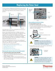
Control Elements<br />
Power Control Panel<br />
Bakeout timer<br />
Bakeout control<br />
buttons<br />
Circuit breakers<br />
Figure 1-6. Upper control panel<br />
Cover lid<br />
Note The buttons themselves have no indicator function. A running<br />
bakeout procedure is indicated by flashing Vacuum and System LEDs at<br />
the front side of the instrument. See Figure 1-4 on page 1-6. ▲<br />
Three circuit breakers are located at the bottom of this control panel.<br />
Table 1-2 shows the parts of the <strong>LTQ</strong> <strong>Orbitrap</strong> <strong>XL</strong> that are protected by<br />
the respective circuit breaker. The proper function of each circuit<br />
breaker is signaled by a dedicated LED in the power control panel (for<br />
example, F1 corresponds to L1).<br />
Table 1-2. Circuit breakers of the <strong>LTQ</strong> <strong>Orbitrap</strong> <strong>XL</strong><br />
Circuit breaker Ampere LED Instrument parts<br />
F1 10 L1 Power Distribution<br />
F2 16 L2 Linear ion trap<br />
F3 10 L3 Multiple socket outlets (Data system, LC, heater,<br />
etc.)<br />
In addition to the system status LEDs at the front side (see Figure 1-4<br />
on page 1-6), the <strong>LTQ</strong> <strong>Orbitrap</strong> <strong>XL</strong> has three power control LEDs<br />
above the Vacuum Pumps switch at the right side. See Figure 1-7. They<br />
indicate whether the corresponding circuit breaker is closed and the<br />
respective parts of the instrument have power. (See Table 1-2 on<br />
page 1-8.)<br />
1-8 <strong>LTQ</strong> <strong>Orbitrap</strong> <strong>XL</strong> <strong>Hardware</strong> <strong>Manual</strong> Thermo Fisher Scientific