LTQ Orbitrap XL Hardware Manual
LTQ Orbitrap XL Hardware Manual
LTQ Orbitrap XL Hardware Manual

Create successful ePaper yourself
Turn your PDF publications into a flip-book with our unique Google optimized e-Paper software.
SPI Bus Termination Board<br />
Table 1-18. Diagnostic LEDs of the High Voltage Power Supply board<br />
No. Name Color Description Normal Operating<br />
Condition<br />
LD1 NO TERM Red SPI bus termination board<br />
missing<br />
LD2 SEND Yellow Interface has been addressed<br />
and sends/receives data<br />
Off<br />
Flashing on SPI bus<br />
data transfer<br />
LD3 SEL Green Board has been addressed Flashing on SPI bus<br />
data transfer<br />
LD4 HV ON Green High voltage is switched on On<br />
Functional Description<br />
Printed Circuit Boards<br />
LD5 POLARITY Green Positive/negative ion mode Off (positive mode)<br />
Various boards communicate via the SPI bus, a serial RS485-based bus<br />
system. The SPI bus termination board reduces unwanted signal<br />
reflections. The boards indicate a missing termination (after<br />
maintenance, for example) by LEDs.<br />
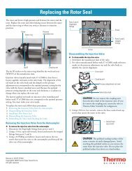
The SPI bus termination board (P/N 208 1480) is located at the bottom<br />
left side of the instrument, below the high voltage power supply board.<br />
See Figure 1-39.<br />
SPI bus termination board<br />
Figure 1-39. High Voltage Power Supply board with SPI Bus Termination<br />
board<br />
Thermo Fisher Scientific <strong>LTQ</strong> <strong>Orbitrap</strong> <strong>XL</strong> <strong>Hardware</strong> <strong>Manual</strong> 1-55