LTQ Orbitrap XL Hardware Manual
LTQ Orbitrap XL Hardware Manual
LTQ Orbitrap XL Hardware Manual

Create successful ePaper yourself
Turn your PDF publications into a flip-book with our unique Google optimized e-Paper software.
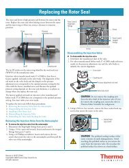
Functional Description<br />
Printed Circuit Boards<br />
Temperature Controller Board<br />
The board switches the injection and measurement voltages for the<br />
central electrode and the detection electrodes of the <strong>Orbitrap</strong>.<br />
Resistor-capacitor circuits on the board convert the switching pulse into<br />
a smooth transition between the voltages.<br />
The diagnostic LEDs listed in Table 1-14 show the status of the voltages<br />
applied to the board as well as some operating states. The position of the<br />
LEDs on the board is indicated by the white rectangles in Figure 1-34<br />
on page 1-47.<br />
Table 1-14. Diagnostic LEDs of the Central Electrode Pulser board<br />
No. Name Color Description Normal Operating<br />
Condition<br />
LD1 TRIG Green Trigger signal indicator Flashing when<br />
scanning<br />
LD2 PS Green 24V Power Supply is OK On<br />
The temperature controller board (P/N 207 8930) is located on the top<br />
left side of the instrument, next to the CLT RF main board. See<br />
Figure 1-32 on page 1-45. The temperature controller board keeps the<br />
temperature of the analyzer chamber to a preset value. A Peltier element<br />
that can be used for heating as well as for cooling is used as an actuator.<br />
Activation is done via the serial SPI (Serial Peripheral Interface) bus.<br />
1-48 <strong>LTQ</strong> <strong>Orbitrap</strong> <strong>XL</strong> <strong>Hardware</strong> <strong>Manual</strong> Thermo Fisher Scientific