LTQ Orbitrap XL Hardware Manual
LTQ Orbitrap XL Hardware Manual
LTQ Orbitrap XL Hardware Manual

You also want an ePaper? Increase the reach of your titles
YUMPU automatically turns print PDFs into web optimized ePapers that Google loves.
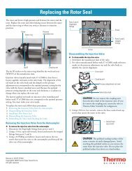
Figure 1-36. CLT RF unit (cover removed)<br />
RF off & feedback board<br />
Functional Description<br />
Printed Circuit Boards<br />
The diagnostic LEDs listed in Table 1-16 show the status of the voltages<br />
applied to the board as well as some operating states. The position of the<br />
LEDs on the board is indicated by the white rectangles in Figure 1-36.<br />
Table 1-16. Diagnostic LEDs of the CLT RF Main board<br />
No. Name Color Description Normal Operating<br />
Condition<br />
LD1 NO TERM Yellow SPI bus termination board<br />
missing<br />
LD2 SEND Yellow Interface has been addressed and<br />
sends/receives data<br />
Thermo Fisher Scientific <strong>LTQ</strong> <strong>Orbitrap</strong> <strong>XL</strong> <strong>Hardware</strong> <strong>Manual</strong> 1-51<br />
Off<br />
Flashing on SPI-bus<br />
data transfer<br />
LD3 SEL Green Board has been addressed Flashing on SPI-bus<br />
data transfer<br />
LD4 RF ON Green RF voltage on On<br />
LD5 NO LOCK Yellow PLL has been not locked 50% intensity<br />
LD6 OVL Yellow RF Amplifier overload Off<br />
LD7 OVHEAT Red Heatsink temperature > 73 °C Off