LTQ Orbitrap XL Hardware Manual
LTQ Orbitrap XL Hardware Manual
LTQ Orbitrap XL Hardware Manual

You also want an ePaper? Increase the reach of your titles
YUMPU automatically turns print PDFs into web optimized ePapers that Google loves.
Functional Description<br />
Control Elements<br />
Main Power Switch<br />
External Connections<br />
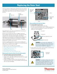
The main power switch must be turned 90° clockwise/anti-clockwise to<br />
switch on/off the instrument (see Figure 1-8). Placing the main power<br />
switch in the Off position turns off all power to the <strong>LTQ</strong> <strong>Orbitrap</strong> <strong>XL</strong><br />
(and linear ion trap as well, including the vacuum pumps).<br />
Off<br />
Figure 1-8. Main power switch<br />
1-10 <strong>LTQ</strong> <strong>Orbitrap</strong> <strong>XL</strong> <strong>Hardware</strong> <strong>Manual</strong> Thermo Fisher Scientific<br />
On<br />
Note When the main power switch is in the Off position, you can secure<br />
it with a padlock or a cable tie (to prevent unintended re-powering when<br />
performing maintenance, for example). ▲<br />
Figure 1-9 on page 1-11 shows the lower right side of the instrument<br />
with the external connections for mains supply, gases, cooling water, and<br />
Ethernet communication.<br />
The power connector for the mains supply is located on the center. The<br />
cooling water ports are located below the power connector. (See also<br />
topic “Cooling Water Circuit” on page 1-28.) A Teflon® hose connects<br />
the instrument to the nitrogen gas supply. An analogous port is used for<br />
the HCD collision gas supply. Metal tubing connects the instrument<br />
with the helium gas supply. (See also topic “Gas Supply” on page 1-25.)<br />
Located at the top are two ports for Ethernet cables for connecting the<br />
<strong>LTQ</strong> <strong>Orbitrap</strong> <strong>XL</strong> and the linear ion trap via an Ethernet hub with the<br />
data system computer.<br />
The exhaust hose from the rotary pumps is led backwards below the<br />
instrument, comes out the back of the instrument, and connects the<br />
pumps to the exhaust system in the laboratory.