CDK-111A-Lite Owner's Guide - Ross Video
CDK-111A-Lite Owner's Guide - Ross Video
CDK-111A-Lite Owner's Guide - Ross Video
- No tags were found...

Create successful ePaper yourself
Turn your PDF publications into a flip-book with our unique Google optimized e-Paper software.
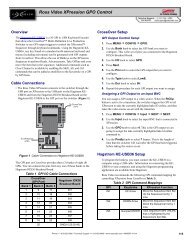
BNC 4 (Tx) RS422/RS485 Jumper Configuration• Bridging pins 3 and 5 removes the 120 Ohm terminator on BNC 4 (Tx) outputfor any position card use.BNC 3 (Rx) RS422/RS485 Jumper Configuration• Bridging pins 2 and 4 installs a 120 Ohm terminator on the Rx (BNC 3) inputfor single card or last card use.• Bridging pins 4 and 6 removes the 120 Ohm terminator on the Rx (BNC 3) inputfor multiple but non-last card use.EDH Insertion Jumper Block (J5)This jumper block is used to insert the EDH information into the PGM and/or PVvideo stream.• Bridging pins 2 and 4 disable EDH insertion on the PGM and PV video outputs.• Bridging pins 4 and 6 enable EDH insertion on the PGM and PV video outputs.This jumper block can also be used to enable or disable STMPE 269M FaultReporting.• Bridging pins 3 and 5 enable STMPE 269M Fault Reporting.• Bridging pins 1 and 3 disable STMPE 269M Fault Reporting.GPI, Panel, Tally Jumper Block (J6)This jumper block is used in conjunction with the menu (software) to define thestatus of BNC 2 – whether it is used as an input for a GPI, an input/output for aControl Panel, or as a Tally output.• Bridging pins 1 and 2 configures the BNC 2 to be used as a GPI input.• Bridging pins 3 and 4 configures the BNC 2 to be used with the DCP111Remote Control Panel unit.• Bridging pins 5 and 6 configures the BNC 2 to be used as a Tally output.Caution — Only one bridge may be installed on the jumperblock J6. Installing more than one bridge may causepermanent damage to the <strong>CDK</strong>-<strong>111A</strong>-<strong>Lite</strong> card. Please notethat contrary to the other jumper blocks, the single bridge onJ6 must be installed horizontally to short circuit either pins 1and 2, or pins 3 and 4, or pins 5 and 6.ImportantThe configuration of this jumper blocks defines the function ofthe BNC 2 connector. The desired operation must also be setupwith the <strong>CDK</strong>-<strong>111A</strong>-<strong>Lite</strong> on-screen menu and must match theconfiguration bridge installed on J6. See Chapter 2,“Installation and Setup” for more details.<strong>CDK</strong>-<strong>111A</strong>-<strong>Lite</strong> • Owner’s <strong>Guide</strong> v4B Appendix C. Specifications • 6-9