Logano plus SB315, SB615, SB745 - Buderus
Logano plus SB315, SB615, SB745 - Buderus
Logano plus SB315, SB615, SB745 - Buderus
- No tags were found...

You also want an ePaper? Increase the reach of your titles
YUMPU automatically turns print PDFs into web optimized ePapers that Google loves.
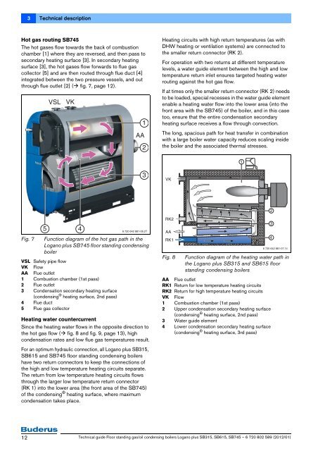
3 Technical descriptionHot gas routing <strong>SB745</strong>The hot gases flow towards the back of combustionchamber [1] where they are reversed, and then pass tosecondary heating surface [3]. In secondary heatingsurface [3], the hot gases flow forwards to flue gascollector [5] and are then routed through flue duct [4]integrated between the two pressure vessels, and outthrough flue outlet [2] ( fig. 7, page 12).VSLVK1AA2Heating circuits with high return temperatures (as withDHW heating or ventilation systems) are connected tothe smaller return connector (RK 2).For operation with two returns at different temperaturelevels, a water guide element between the high and lowtemperature return inlet ensures targeted heating waterrouting against the hot gas flow.If at times only the smaller return connector (RK 2) needsto be loaded, special recesses in the water guide elementenable a heating water flow into the lower area (into thefront area with the <strong>SB745</strong>) of the boiler, and in this casetoo, ensure that the entire condensation secondaryheating surface receives a flow through convection.The long, spacious path for heat transfer in combinationwith a large boiler water capacity reduces scaling insidethe boiler and the associated thermal stresses.13VK2Fig. 75Function diagram of the hot gas path in the<strong>Logano</strong> <strong>plus</strong> <strong>SB745</strong> floor standing condensingboilerVSL Safety pipe flowVK FlowAA Flue outlet1 Combustion chamber (1st pass)2 Flue outlet3 Condensation secondary heating surface(condensing p heating surface, 2nd pass)4 Flue duct5 Flue gas collector46 720 642 881-06.2THeating water countercurrentSince the heating water flows in the opposite direction tothe hot gas flow ( fig. 8 and fig. 9, page 13), highcondensation rates and low flue gas temperatures result.For an optimum hydraulic connection, all <strong>Logano</strong> <strong>plus</strong> <strong>SB315</strong>,<strong>SB615</strong> and <strong>SB745</strong> floor standing condensing boilershave two return connectors to keep the connections ofthe high and low temperature heating circuits separate.The return from low temperature heating circuits flowsthrough the larger low temperature return connector(RK 1) into the lower area (the front area of the <strong>SB745</strong>)of the condensing p heating surface, where maximumcondensation takes place.RK2AARK1Fig. 8Function diagram of the heating water path inthe <strong>Logano</strong> <strong>plus</strong> <strong>SB315</strong> and <strong>SB615</strong> floorstanding condensing boilersAA Flue outletRK1 Return for low temperature heating circuitsRK2 Return for high temperature heating circuitsVK Flow1 Combustion chamber (1st pass)2 Upper condensation secondary heating surface(condensing p heating surface, 2nd pass)3 Water guide element4 Lower condensation secondary heating surface(condensing p heating surface, 3rd pass)346 720 642 881-07.1il12Technical guide Floor standing gas/oil condensing boilers <strong>Logano</strong> <strong>plus</strong> <strong>SB315</strong>, <strong>SB615</strong>, <strong>SB745</strong> – 6 720 802 589 (2012/01)