- Page 1:
ACCESS CONTROL SYSTEMSCONVENTIONAL
- Page 5 and 6:
LASTFLOOR5GROUNDFLOORTELEPHONE INTH
- Page 7:
DIRECT CONNECTIONS BETWEEN THE PANE
- Page 10 and 11:
1 2 34 5 67 8 9C 0POSSIBILITY OF IN
- Page 12:
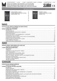
COMMUNICATION SYSTEM WITH 6+N+COAXI
- Page 16 and 17:
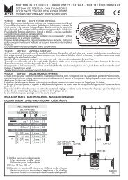
230V~ ±10%50-60HzDC OUT : 15V0.2 A
- Page 18 and 19:
OFFONOFFONSYSTEM ON STANDBY. NO CAL
- Page 20 and 21:
OFFONOFFONOFFONOFFONOFFONOFFONTRANS
- Page 22 and 23:
1 2 347 8 9C 01 2 347 8 9C 01 2 347
- Page 24 and 25:
1 2 347 8 9C 01 2 347 8 9C 01 2 34
- Page 27 and 28:
AUTO SWITCH-ON FUNCTION (monitors)T
- Page 29 and 30:
TV DOOR ENTRY SYSTEM INSTALLATIONST
- Page 31 and 32:
cod.9730015T1+ T1 T1 T1+ T1+ T1 T1+
- Page 33 and 34:
ARRIBAUPHAUT230V~ ±10%DC OUT50-60H
- Page 35 and 36:
ELECTRONIC CALL SYSTEM84 mmCod. 960
- Page 37:
84 mmCod. 9600012TES-002ELECTRONIC
- Page 40 and 41:
84 mmCod. 9600011TUN-002UNIVERSAL T
- Page 42:
ACCESSORIES FOR TELEPHONESDESKTOP S
- Page 45 and 46:
CC1CC1Monitor connectorTERMINALS IN
- Page 47 and 48:
ARRIBAUPHAUTCod. 9730034MAE-900GENE
- Page 49 and 50:
12 VV+15 Vcod.9730016T1+ T1 T1+ T1
- Page 51 and 52:
A brief description of each entranc
- Page 53 and 54:
SINGLE BLANK MODULES78.5 mm128 mm12
- Page 55 and 56:
126.5 mm128 mm12 mmCod. 9670122 MDN
- Page 57 and 58:
UPPER MODULES WITH CARD-HOLDER AND
- Page 59 and 60:
AUDIO UNITS IN ENTRANCE PANELS WITH
- Page 61 and 62:
21Cod. 9610030GRF-204ELECTRONIC AUD
- Page 63 and 64:
Description of terminals and typica
- Page 65 and 66:
Cod. 9640009TCB-021GENERIC COLOUR V
- Page 67 and 68:
Cod. 9640008TCB-050GENERIC COLOUR V
- Page 69 and 70:
ENTRANCE PANEL LOWER MODULES212121T
- Page 71 and 72:
LOWER ENTRANCE PANEL MODULES WITH C
- Page 73 and 74:
SINGLE MODULES WITH CARD-HOLDER78.5
- Page 75 and 76:
OFFONTELEPHONES FOR CONCIERGE SYSTE
- Page 77 and 78:
ARRIBAUPHAUTARRIBAUPHAUTARRIBAUPHAU
- Page 79 and 80:
COVER FRAMES FOR ENTRANCE PANELFram
- Page 81 and 82:
25 mmCod. 9730033 ESC-010LONG SHIEL
- Page 83 and 84:
BUZZING CALL50 mmCód. 9730020AAL-2
- Page 85 and 86:
Ctrl15A / 250V~40 mmS2 S52 588 mm6A
- Page 87 and 88:
Made in SpainCALL ADAPTER ACCESSORI
- Page 89 and 90:
70 mm111 mm42 mm230V~ ±10%50-60HzD
- Page 91 and 92:
90 mm230 V V106 mmCod. 9620002ALA-0
- Page 93:
Description of terminals and techni
- Page 96 and 97:
ARRIBAUPHAUTARRIBAUPHAUTARRIBAUPHAU
- Page 98 and 99:
ARRIBAUPHAUTARRIBAUPHAUTARRIBAUPHAU
- Page 100 and 101:
ARRIBAUPHAUTARRIBAUPHAUTARRIBAUPHAU
- Page 102 and 103:
ARRIBAUPHAUTARRIBAUPHAUTARRIBAUPHAU
- Page 104 and 105:
4MECHANICAL ASSEMBLYACCESSORIES FOR
- Page 106 and 107:
SURFACE WALL-MOUNTED BOXBREAKING TH
- Page 108 and 109:
RAIN-SHIELDSRAIN-SHIELDS FOR FLUSH-
- Page 110 and 111:
ENTRANCE PANELS WITH PUSHBUTTONSCON
- Page 112 and 113:
POSITIONING THE ENTRANCE PANELSPOSI
- Page 114 and 115:
If a rain-shield is being added, fi
- Page 116 and 117:
Once the electrical connections and
- Page 118 and 119:
CONCIERGE SYSTEMS: TELEPHONES FOR C
- Page 120 and 121:
Separate the upper and lower decora
- Page 122 and 123:
POSITIONING THE TELEPHONE FOR CONCI
- Page 124 and 125:
ASSEMBLING THE COVER OF THE TELEPHO
- Page 126 and 127: PUSHBUTTONSASSEMBLING THE PUSHBUTTO
- Page 128 and 129: cod.9730015T1+ T1 T1 T1+ T1+ T1 T1+
- Page 130 and 131: TELEPHONES FOR HOUSES AND FLATSDISA
- Page 132 and 133: Close the telephone and fix the cov
- Page 134 and 135: COVER FRAMES FOR MONITORSPLACE AND
- Page 136 and 137: INSTALLATION ON A STANDARD ELECTRIC
- Page 138 and 139: Put the receiver in place and conne
- Page 140 and 141: CtrlCtrlCtrlSWITCH-SELECTOR ACCESSO
- Page 142 and 143: MODULATORS FOR TV DOOR ENTRY INSTAL
- Page 144 and 145: CONNECTIONS AND ASSEMBLY OF TERMINA
- Page 146 and 147: ADJUSTMENTSelecting the call toneTh
- Page 148 and 149: Electronic door entry with concierg
- Page 150 and 151: Description of connections:Electron
- Page 152 and 153: Adjusting the volume controlsThe au
- Page 154 and 155: Replacement installationsPower supp
- Page 156 and 157: VIDEO UNITS IN ENTRANCE PANELS WITH
- Page 158 and 159: ADJUSTMENTControl of the angle of v
- Page 160 and 161: ADJUSTMENTAdjusting the volume cont
- Page 162 and 163: TWISTED PAIRTAP-OFF DIV-034CONNECTI
- Page 164 and 165: TELEPHONES FOR HOUSES AND FLATSTELE
- Page 166 and 167: Electronic door entry installations
- Page 168 and 169: TELEPHONE FOR INTERNAL COMMUNICATIO
- Page 170 and 171: Replacement installationsNext telep
- Page 172 and 173: ADJUSTMENTSReplacement installation
- Page 174 and 175: 5A / 250V~ACCESSORIES FOR MONITORSD
- Page 178 and 179: Distribution of the video signal vi
- Page 180 and 181: Description of connections:CC1Next
- Page 182 and 183: DIV-034cod.9730015T1+ T1 T1 T1+ T1+
- Page 184 and 185: ELECTRONIC ACCESSORIESCALL EXTENSIO
- Page 186 and 187: COMPATIBILITY TABLEMODELALCAD AAL-2
- Page 188 and 189: ACTIVATING BY EXTERNAL CONTROL SIGN
- Page 190 and 191: Description of connections:Power su
- Page 192 and 193: ADJUSTMENTSelecting the output chan
- Page 194 and 195: POWER SUPPLY UNITSPOWER SUPPLY ALA-
- Page 196 and 197: 6DIAGRAMSGENERAL POINTS CONCERNING
- Page 198 and 199: STANDARD INSTALLATION IN BUILDINGCO
- Page 200 and 201: INSTALLATION IN BUILDING WITH SEVER
- Page 202 and 203: VHOUSING ESTATE WITH 3 BUILDINGS. 1
- Page 204 and 205: DOOR ENTRY INSTALLATIONS WITH CONCI
- Page 206 and 207: INSTALLATION IN BUILDING WITH SEVER
- Page 208 and 209: DOOR ENTRY INSTALLATIONS. BUZZING C
- Page 210 and 211: INSTALLATION IN BUILDING WITH SEVER
- Page 212 and 213: HOUSING ESTATE WITH 3 BUILDINGS. 1
- Page 214 and 215: Made in SpainMade in SpainBUILDING
- Page 216 and 217: DOOR ENTRY INSTALLATIONS WITH CONFI
- Page 218 and 219: INSTALLATION IN BUILDING WITH SEVER
- Page 220 and 221: HOUSING ESTATE WITH 3 BUILDINGS. 1
- Page 222 and 223: VVVHOUSING ESTATE WITH 3 BUILDINGS.
- Page 224 and 225: 1 2 34 5 67 8 9C 01 2 34 5 67 8 9C
- Page 226 and 227:
1 2 34 5 67 8 9C 02 34 5 67 8 9C 0S
- Page 228 and 229:
1 2 34 5 67 8 9C 02 34 5 67 8 9C 0E
- Page 230 and 231:
VIDEO DOOR ENTRY INSTALLATIONS. ELE
- Page 232 and 233:
STANDARD INSTALLATION IN BUILDING:
- Page 234 and 235:
INSTALLATION IN BUILDING WITH SEVER
- Page 236 and 237:
INSTALLATION IN BUILDING WITH 2 POI
- Page 238 and 239:
HOUSING ESTATE WITH 3 BUILDINGS WIT
- Page 240 and 241:
19J1HOUSING ESTATE WITH 3 BUILDINGS
- Page 242 and 243:
cod. 9610001STANDARD INSTALLATION I
- Page 244 and 245:
STANDARD INSTALLATION IN BUILDING:
- Page 246 and 247:
DIV-034cod.9730015T1+ T1 T1 T1+ T1+
- Page 248 and 249:
DIV-034cod.9730015T1+ T1 T1 T1+ T1+
- Page 250 and 251:
DIV-034cod.9730015T1+ T1 T1 T1+ T1+
- Page 252 and 253:
HOUSING ESTATE WITH 3 BUILDINGS WIT
- Page 254 and 255:
DOOR ENTRY INSTALLATIONS WITH CONCI
- Page 256 and 257:
1 2 34 5 67 8 9C 01 2 34 5 67 8 9C
- Page 258 and 259:
CONVENTIONAL SYSTEM 6+N+TWISTED PAI
- Page 260 and 261:
WIRED DIAGRAMINSTALLATION WITH TAP-
- Page 262 and 263:
WIRED DIAGRAMINSTALLATION WITH TAP-
- Page 264 and 265:
R1WIRED DIAGRAMA J1A J1A J1R1SCM-01
- Page 266 and 267:
R1WIRED DIAGRAMA J1A J1A J1R1SCM-02
- Page 268 and 269:
DOOR ENTRY INSTALLATIONS WITH CONCI
- Page 270 and 271:
1 2 34 5 67 8 9C 0DOOR ENTRY INSTAL
- Page 272 and 273:
CONVENTIONAL SYSTEM 6+N+TWISTED PAI
- Page 274 and 275:
INSTALLATIONS WITH AUDIO UNIT GRF-2
- Page 276 and 277:
DOOR ENTRY INSTALLATIONS WITH CONFI
- Page 278 and 279:
OPENING OF A SECOND DOOR FROM THE T
- Page 280 and 281:
ACTIVATING A 12VAC ELECTRIC LOCKUse
- Page 282 and 283:
DOOR ENTRY INSTALLATIONSWIRED DIAGR
- Page 284 and 285:
ACTIVATING A LIGHT, BELL OR SIREN W
- Page 286 and 287:
230V~ ±10%50-60HzDC OUT : 15V0.2 A
- Page 288 and 289:
TV DOOR ENTRY INSTALLATION IN A STA
- Page 290 and 291:
INSTALLATION IN BUILDING WITH SEVER
- Page 292 and 293:
You cannot hear one of the telephon
- Page 294 and 295:
ELECTRONIC DOOR ENTRY INSTALLATIONS
- Page 296 and 297:
ELECTRONIC DOOR ENTRY INSTALLATIONS
- Page 298 and 299:
INTERNAL COMMUNICATION INSTALLATION
- Page 300 and 301:
ELECTRONIC VIDEO DOOR ENTRY INSTALL
- Page 302 and 303:
INSTALLATION IN BUILDING WITH SEVER
- Page 304 and 305:
ELECTRONIC VIDEO DOOR ENTRY INSTALL
- Page 306 and 307:
INSTALLATION IN BUILDING WITH SEVER
- Page 308 and 309:
TV DOOR ENTRY INSTALLATIONSSTANDARD