

Top-down digital design flow - Microelectronic Systems Laboratory
Top-down digital design flow - Microelectronic Systems Laboratory
Top-down digital design flow - Microelectronic Systems Laboratory

You also want an ePaper? Increase the reach of your titles
YUMPU automatically turns print PDFs into web optimized ePapers that Google loves.
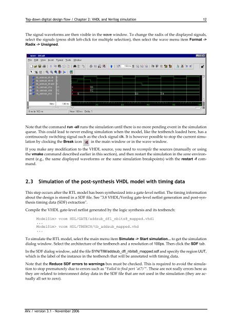
<strong>Top</strong>-<strong>down</strong> <strong>digital</strong> <strong>design</strong> <strong>flow</strong> / Chapter 2: VHDL and Verilog simulation 12The signal waveforms are then visible in the wave window. To change the radix of the displayed signals,select the signals (press shift left‐click for multiple selection), then select the wave menu item Format ->Radix -> Unsigned.Note that the command run -all runs the simulation until there is no more pending event in the simulationqueue. This could lead to never ending simulation when the model, like the testbench loaded here, has acontinuously switching signal such as the clock signal clk. It is however possible to stop the current simulationby clocking the Break icon in the main window or in the wave window.If you make any modification to the VHDL source, you need to recompile the sources (manually or usingthe vmake command described earlier in this section), and then restart the simulation in the same environment(e.g., the same displayed waveforms or the same simulation breakpoints) with the restart -f command.2.3 Simulation of the post-synthesis VHDL model with timing dataThis step occurs after the RTL model has been synthesized into a gate‐level netlist. The timing informationabout the <strong>design</strong> is stored in a SDF file. See ʺ3.8 VHDL/Verilog gate‐level netlist generation and post‐synthesistiming data (SDF) extractionʺ.Compile the VHDL gate‐level netlist generated by the logic synthesis and its testbench:ModelSim> vcom HDL/GATE/addsub_dfl_nbits8_mapped.vhdl...ModelSim> vcom HDL/TBENCH/tb_addsub_mapped.vhd...To simulate the RTL model, select the main menu item Simulate -> Start simulation... to get the simulationdialog window. Select the architecture of the testbench and a resolution of 100ps. Then click the SDF tab.In the SDF dialog window, add the file SYN/TIM/addsub_dfl_nbits8_mapped.sdf and specify the region UUT,which is the label of the instance in the testbench that will be annotated with timing data.Note that the Reduce SDF errors to warnings box must be checked. This is required to avoid the simulationto stop prematurely due to errors such as “Failed to find port ʹa(7)ʹ”. These are not really errors here asthey are related to interconnect delay data in the SDF file that are not used in the simulation (they are actuallyall set to zero).AVx / version 3.1 - November 2006


