

Top-down digital design flow - Microelectronic Systems Laboratory
Top-down digital design flow - Microelectronic Systems Laboratory
Top-down digital design flow - Microelectronic Systems Laboratory

Create successful ePaper yourself
Turn your PDF publications into a flip-book with our unique Google optimized e-Paper software.
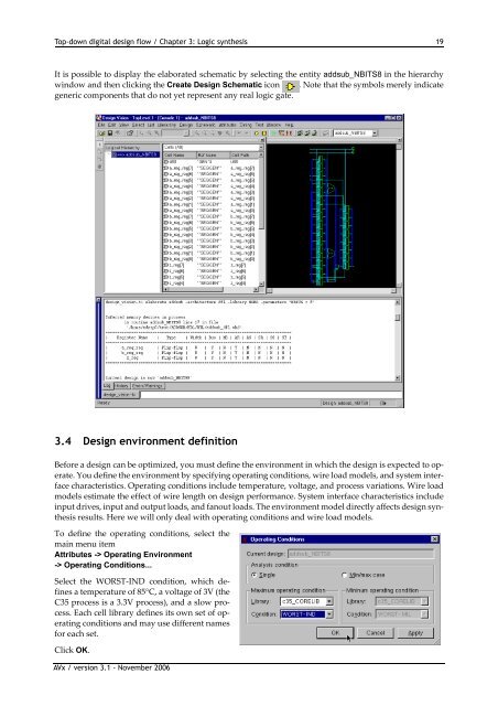
<strong>Top</strong>-<strong>down</strong> <strong>digital</strong> <strong>design</strong> <strong>flow</strong> / Chapter 3: Logic synthesis 19It is possible to display the elaborated schematic by selecting the entity addsub_NBITS8 in the hierarchywindow and then clicking the Create Design Schematic icon . Note that the symbols merely indicategeneric components that do not yet represent any real logic gate.3.4 Design environment definitionBefore a <strong>design</strong> can be optimized, you must define the environment in which the <strong>design</strong> is expected to operate.You define the environment by specifying operating conditions, wire load models, and system interfacecharacteristics. Operating conditions include temperature, voltage, and process variations. Wire loadmodels estimate the effect of wire length on <strong>design</strong> performance. System interface characteristics includeinput drives, input and output loads, and fanout loads. The environment model directly affects <strong>design</strong> synthesisresults. Here we will only deal with operating conditions and wire load models.To define the operating conditions, select themain menu itemAttributes -> Operating Environment-> Operating Conditions...Select the WORST‐IND condition, which definesa temperature of 85°C, a voltage of 3V (theC35 process is a 3.3V process), and a slow process.Each cell library defines its own set of operatingconditions and may use different namesfor each set.Click OK.AVx / version 3.1 - November 2006


