

Top-down digital design flow - Microelectronic Systems Laboratory
Top-down digital design flow - Microelectronic Systems Laboratory
Top-down digital design flow - Microelectronic Systems Laboratory

You also want an ePaper? Increase the reach of your titles
YUMPU automatically turns print PDFs into web optimized ePapers that Google loves.
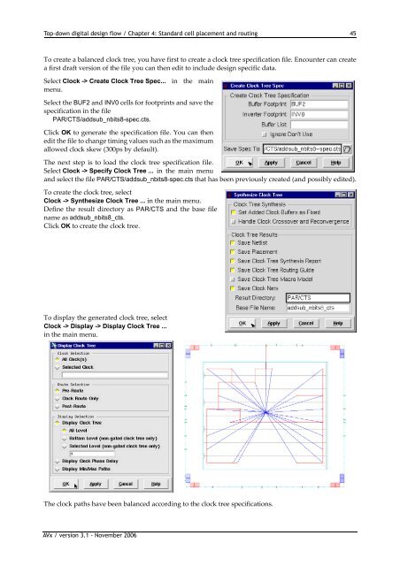
<strong>Top</strong>-<strong>down</strong> <strong>digital</strong> <strong>design</strong> <strong>flow</strong> / Chapter 4: Standard cell placement and routing 45To create a balanced clock tree, you have first to create a clock tree specification file. Encounter can createa first draft version of the file you can then edit to include <strong>design</strong> specific data.Select Clock -> Create Clock Tree Spec... in the mainmenu.Select the BUF2 and INV0 cells for footprints and save thespecification in the filePAR/CTS/addsub_nbits8-spec.cts.Click OK to generate the specification file. You can thenedit the file to change timing values such as the maximumallowed clock skew (300ps by default).The next step is to load the clock tree specification file.Select Clock->SpecifyClockTree... in the main menuand select the file PAR/CTS/addsub_nbits8-spec.cts that has been previously created (and possibly edited).To create the clock tree, selectClock->SynthesizeClockTree... in the main menu.Define the result directory as PAR/CTS and the base filename as addsub_nbits8_cts.Click OK to create the clock tree.To display the generated clock tree, selectClock -> Display -> Display Clock Tree ...in the main menu.The clock paths have been balanced according to the clock tree specifications.AVx / version 3.1 - November 2006


