

Integrator/CP User Guide - ARM Information Center
Integrator/CP User Guide - ARM Information Center
Integrator/CP User Guide - ARM Information Center

Create successful ePaper yourself
Turn your PDF publications into a flip-book with our unique Google optimized e-Paper software.
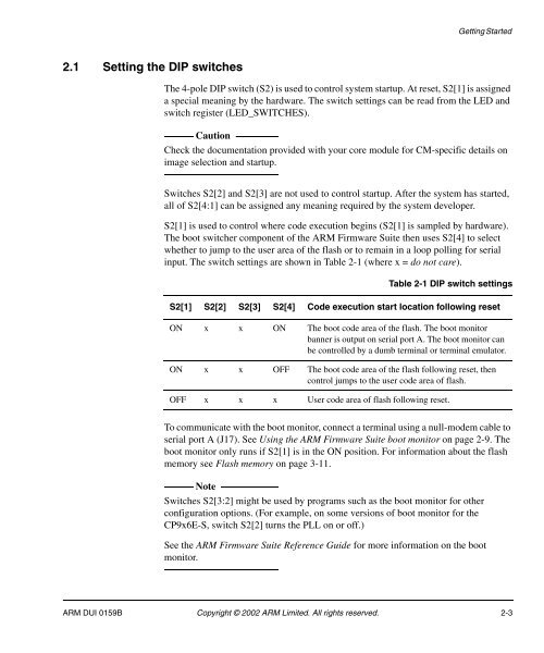
Getting Started2.1 Setting the DIP switchesThe 4-pole DIP switch (S2) is used to control system startup. At reset, S2[1] is assigneda special meaning by the hardware. The switch settings can be read from the LED andswitch register (LED_SWITCHES).CautionCheck the documentation provided with your core module for CM-specific details onimage selection and startup.Switches S2[2] and S2[3] are not used to control startup. After the system has started,all of S2[4:1] can be assigned any meaning required by the system developer.S2[1] is used to control where code execution begins (S2[1] is sampled by hardware).The boot switcher component of the <strong>ARM</strong> Firmware Suite then uses S2[4] to selectwhether to jump to the user area of the flash or to remain in a loop polling for serialinput. The switch settings are shown in Table 2-1 (where x = do not care).Table 2-1 DIP switch settingsS2[1] S2[2] S2[3] S2[4] Code execution start location following resetON x x ON The boot code area of the flash. The boot monitorbanner is output on serial port A. The boot monitor canbe controlled by a dumb terminal or terminal emulator.ON x x OFF The boot code area of the flash following reset, thencontrol jumps to the user code area of flash.OFF x x x <strong>User</strong> code area of flash following reset.To communicate with the boot monitor, connect a terminal using a null-modem cable toserial port A (J17). See Using the <strong>ARM</strong> Firmware Suite boot monitor on page 2-9. Theboot monitor only runs if S2[1] is in the ON position. For information about the flashmemory see Flash memory on page 3-11.NoteSwitches S2[3:2] might be used by programs such as the boot monitor for otherconfiguration options. (For example, on some versions of boot monitor for the<strong>CP</strong>9x6E-S, switch S2[2] turns the PLL on or off.)See the <strong>ARM</strong> Firmware Suite Reference <strong>Guide</strong> for more information on the bootmonitor.<strong>ARM</strong> DUI 0159B Copyright © 2002 <strong>ARM</strong> Limited. All rights reserved. 2-3


