

Integrator/CP User Guide - ARM Information Center
Integrator/CP User Guide - ARM Information Center
Integrator/CP User Guide - ARM Information Center

Create successful ePaper yourself
Turn your PDF publications into a flip-book with our unique Google optimized e-Paper software.
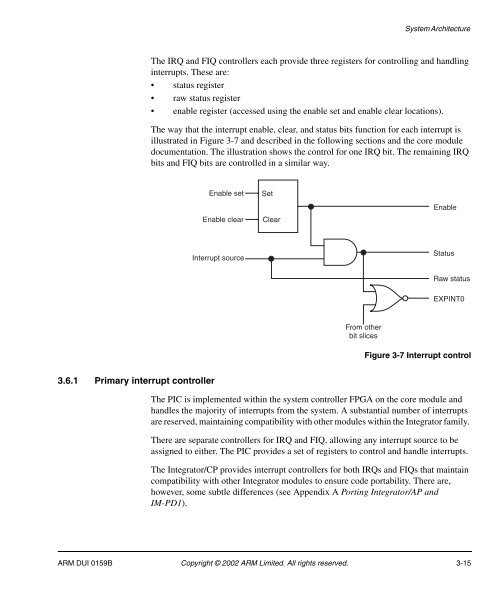
System ArchitectureThe IRQ and FIQ controllers each provide three registers for controlling and handlinginterrupts. These are:• status register• raw status register• enable register (accessed using the enable set and enable clear locations).The way that the interrupt enable, clear, and status bits function for each interrupt isillustrated in Figure 3-7 and described in the following sections and the core moduledocumentation. The illustration shows the control for one IRQ bit. The remaining IRQbits and FIQ bits are controlled in a similar way.Enable setEnable clearSetClearEnableInterrupt sourceStatusRaw statusEXPINT0From otherbit slicesFigure 3-7 Interrupt control3.6.1 Primary interrupt controllerThe PIC is implemented within the system controller FPGA on the core module andhandles the majority of interrupts from the system. A substantial number of interruptsare reserved, maintaining compatibility with other modules within the <strong>Integrator</strong> family.There are separate controllers for IRQ and FIQ, allowing any interrupt source to beassigned to either. The PIC provides a set of registers to control and handle interrupts.The <strong>Integrator</strong>/<strong>CP</strong> provides interrupt controllers for both IRQs and FIQs that maintaincompatibility with other <strong>Integrator</strong> modules to ensure code portability. There are,however, some subtle differences (see Appendix A Porting <strong>Integrator</strong>/AP andIM-PD1).<strong>ARM</strong> DUI 0159B Copyright © 2002 <strong>ARM</strong> Limited. All rights reserved. 3-15


