

Integrator/CP User Guide - ARM Information Center
Integrator/CP User Guide - ARM Information Center
Integrator/CP User Guide - ARM Information Center

Create successful ePaper yourself
Turn your PDF publications into a flip-book with our unique Google optimized e-Paper software.
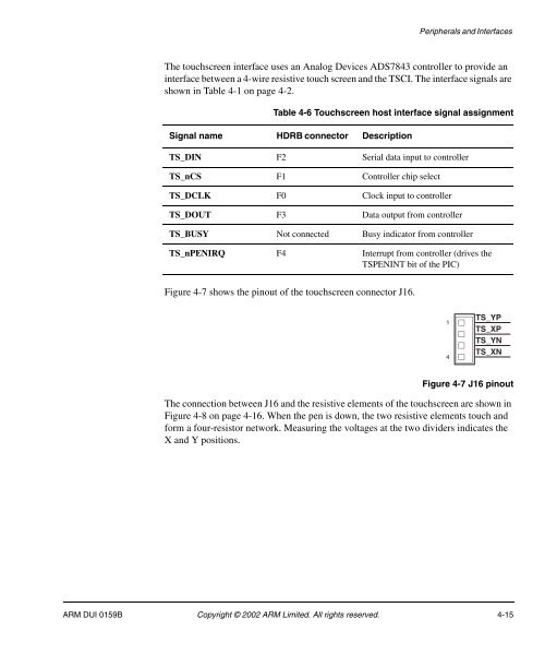
Peripherals and InterfacesThe touchscreen interface uses an Analog Devices ADS7843 controller to provide aninterface between a 4-wire resistive touch screen and the TSCI. The interface signals areshown in Table 4-1 on page 4-2.Table 4-6 Touchscreen host interface signal assignmentSignal name HDRB connector DescriptionTS_DIN F2 Serial data input to controllerTS_nCS F1 Controller chip selectTS_DCLK F0 Clock input to controllerTS_DOUT F3 Data output from controllerTS_BUSY Not connected Busy indicator from controllerTS_nPENIRQ F4 Interrupt from controller (drives theTSPENINT bit of the PIC)Figure 4-7 shows the pinout of the touchscreen connector J16.14TS_YPTS_XPTS_YNTS_XNFigure 4-7 J16 pinoutThe connection between J16 and the resistive elements of the touchscreen are shown inFigure 4-8 on page 4-16. When the pen is down, the two resistive elements touch andform a four-resistor network. Measuring the voltages at the two dividers indicates theX and Y positions.<strong>ARM</strong> DUI 0159B Copyright © 2002 <strong>ARM</strong> Limited. All rights reserved. 4-15


