

Integrator/CP User Guide - ARM Information Center
Integrator/CP User Guide - ARM Information Center
Integrator/CP User Guide - ARM Information Center

You also want an ePaper? Increase the reach of your titles
YUMPU automatically turns print PDFs into web optimized ePapers that Google loves.
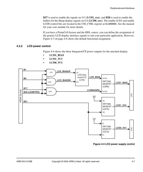
Peripherals and InterfacesB27 is used to enable the signals on J13 (LCD1_xxx), and B28 is used to enable thebuffers for the Sharp display signals on J14 (LCD0_xxx). The enable LCD1 and enableLCD0 control bits are located in the CM_CTRL register at 0x1000000C. See the manualfor your core module for more details.If you have a PrimeCell license and the HDL source, you can define the assignment ofthe generic LCD display interface signals to suit your particular application. However,Figure 4-3 on page 4-6 shows the default functional assignment.4.3.2 LCD power controlFigure 4-4 shows the three <strong>Integrator</strong>/<strong>CP</strong> power outputs for the attached display:• LCD1_BIAS• LCD1_3V3• LCD0_3V3.HDRA SocketB1B9B17B30 (n24BITEN)B31(U3)(U3)(U3)LCD_BIASUPLCD_BIASDNUPLCD biascontrol IC(U18)DNLCD_BIASLCDBIASEN3V3S1/S2IRF7306MOSFET(U26b)G1/G2S2IRF7306MOSFET(U27b)D2D2LCD1_BIASLCD1_3V3J13G23V3S1IRF7306MOSFET(U27a)D1LCD0_3V3J14G1Figure 4-4 LCD power supply control<strong>ARM</strong> DUI 0159B Copyright © 2002 <strong>ARM</strong> Limited. All rights reserved. 4-7


