- Page 1 and 2:
SERIES9600 SERVICE MANUAL ERROR CO
- Page 3:
START-UP AND SOFTWARE BOOT Loading
- Page 6 and 7:
SRAM Card Error Codes If an error o
- Page 9 and 10:
Event Codes & Messages The software
- Page 12 and 13:
Event Codes & Messages (Cont.) CODE
- Page 15 and 16:
Event Codes & Messages (Cont.) CODE
- Page 17:
Event Codes & Messages (Cont.) 57 W
- Page 20 and 21:
Low Battery Charge Messages Under m
- Page 23:
Error Messages During Operation (Co
- Page 26 and 27:
Status Menu Chart Use the following
- Page 28 and 29:
PIO Status Use this menu to read th
- Page 30:
Speaker Pitch This menu allows the
- Page 34 and 35:
386 AMI BIOS Post Code Table These
- Page 36 and 37:
386 AMI BIOS Post Code Table (Cont.
- Page 38:
386 AMI BIOS Post Code Table (Cont.
- Page 42:
Nobrk.com Error Codes (Executed by
- Page 45:
Loadip.Exe (Executed By Autoexec.Ba
- Page 49:
Critical Errors Code Description Po
- Page 53:
ii 9600 System Service Manual © De
- Page 57 and 58:
INTRODUCTION PURPOSE This manual co
- Page 59 and 60:
Introduction 3 SAFETY PRECAUTIONS T
- Page 61 and 62:
Introduction 5 EXPLOSION HAZARDS WA
- Page 63 and 64:
Introduction 7 WARNING SYMBOLS The
- Page 66 and 67:
Introduction 9 UNAUTHORIZED MODIFIC
- Page 69 and 70:
SYSTEM OVERVIEW OVERVIEW This secti
- Page 71:
System Overview 3 • Digital image
- Page 74 and 75:
System Overview 5 • Auto and manu
- Page 76:
System Overview 7 Video Monitors
- Page 79 and 80:
System Overview 9 System Configurat
- Page 81 and 82:
System Overview 11 NEUROVASCULAR MO
- Page 84 and 85:
System Overview 13 SYSTEM OPERATION
- Page 86 and 87:
System Overview 15 CAMERA ROTATION
- Page 89 and 90:
System Overview 17 WORKSTATION CONT
- Page 91 and 92:
System Overview 19 A V E R A G I N
- Page 93 and 94:
System Overview 21 HELP PATIENT (AN
- Page 95 and 96:
System Overview 23 Trackpad Panels
- Page 97:
System Overview 25 Lenzar Hardcopy
- Page 100:
System Overview 27 CONTROL PANEL WA
- Page 103:
System Overview 29 WORKSTATION COVE
- Page 107:
System Overview 31 3. Pull the left
- Page 110:
System Overview 33 8. Remove the mo
- Page 114 and 115:
System Overview 35 2. Grasp the top
- Page 117 and 118:
System Overview 37 COMPONENT LOCATI
- Page 120 and 121:
System Overview 39 Mobile C-Arm Com
- Page 122 and 123: System Overview 41 WORKSTATION COMP
- Page 124 and 125: System Overview 43 Power/Motor Rela
- Page 126 and 127: System Overview 45 IR Receiver PCB
- Page 129 and 130: POWER DISTRIBUTION OVERVIEW The inf
- Page 131 and 132: Power Distribution 3 WORKSTATION CI
- Page 133 and 134: Power Distribution 5 WORKSTATION IS
- Page 135 and 136: Power Distribution 7 POWER CONTROL
- Page 137 and 138: Power Distribution 9 F1 CB1 CB2 CB3
- Page 139 and 140: Power Distribution 11 PS4 (+24 VDC)
- Page 141 and 142: Power Distribution 13 Figure 8 DC P
- Page 144: Power Distribution 15 PS1 (5V and 1
- Page 147: Power Distribution 17 115VAC_PH_SW
- Page 150 and 151: Power Distribution 19 120 VAC DC 7
- Page 153: Power Distribution 21 S/N 69-1001 a
- Page 156 and 157: Power Distribution 23 L N 1 L D 1 G
- Page 158: Power Distribution 25 PS2 (24V) S/N
- Page 161 and 162: Power Distribution 27 Current Sensi
- Page 163 and 164: Power Distribution 29 Battery Charg
- Page 165 and 166: Power Distribution 31 S/N 69-1001 a
- Page 167 and 168: Power Distribution 33 Battery Charg
- Page 169 and 170: Power Distribution 35 BATTERY CHARG
- Page 171: 2 C-Arm Control • Mainframe Mothe
- Page 175: C-Arm Control 5 CONTROL PANEL The M
- Page 178 and 179: C-Arm Control 7 MEMORY AND ADDRESSI
- Page 181 and 182: C-Arm Control 9 The following illus
- Page 183 and 184: C-Arm Control 11 O E C Ḏ IA S O N
- Page 185 and 186: C-Arm Control 13 CONTROL PANEL PROC
- Page 187 and 188: C-Arm Control 15 CARD RACK REAR COV
- Page 189 and 190: C-Arm Control 17 U51 is an interrup
- Page 191: C-Arm Control 19 wait for the A/D p
- Page 195 and 196: C-Arm Control 21 44 UX X U 2 0 X U
- Page 197: C-Arm Control 23 ANALOG INTERFACE P
- Page 200 and 201: C-Arm Control 25 D/A SECTION U18 an
- Page 203 and 204: C-Arm Control 27 PIO SECTION Severa
- Page 206: C-Arm Control 29 BIT # PIN # SIGNAL
- Page 209 and 210: C-Arm Control 31 ASSY 00-876740- (
- Page 212 and 213: C-Arm Control 33 P7 M O D E L 9 4 0
- Page 214 and 215: C-Arm Control 35 SYSTEM COMMUNICATI
- Page 216 and 217: C-Arm Control 37 Technique Processo
- Page 218: C-ARM SOFTWARE OVERVIEW The 9600 C-
- Page 221 and 222: C-Arm Software 3 EEPROM USAGE The e
- Page 223 and 224:
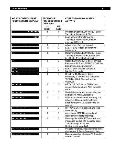
C-Arm Software 5 X-RAY CONTROL PANE
- Page 225 and 226:
C-Arm Software 7 MAINFRAME MENU The
- Page 227:
C-Arm Software 9 CAUTION: Use this
- Page 230:
C-Arm Software 11 F - Examine Event
- Page 233 and 234:
C-Arm Software 13 ABS INDEX TABLE E
- Page 235:
C-Arm Software 15 EUR_STD.ABS EUR_L
- Page 238 and 239:
C-Arm Software 17 COPY FILES FROM S
- Page 240 and 241:
C-Arm Software 19 Hot-Byte Set (1)
- Page 242 and 243:
INTERLOCK/STATOR OVERVIEW This sect
- Page 244 and 245:
Interlocks / Stator 3 GENERATOR INT
- Page 246 and 247:
Interlocks / Stator 5 +24V INTERLOC
- Page 249 and 250:
Interlocks / Stator 7 PRE-CHARGE OV
- Page 251:
Interlocks / Stator 9 STATOR OVERVI
- Page 254 and 255:
Interlocks / Stator 11 STATOR CURRE
- Page 256 and 257:
Interlocks / Stator 13 C1 C3 C4 R1
- Page 258 and 259:
Interlocks / Stator 15 R5 CR15 1 R
- Page 260 and 261:
2 X-ray On / Disable Power Signal I
- Page 263 and 264:
4 X-ray On / Disable X-RAY ON X-RAY
- Page 265:
6 X-ray On / Disable SIGNAL X-RAY X
- Page 268 and 269:
2 kV Generation CONTROL INPUTS Init
- Page 270:
4 kV Generation KV SENSE Detects th
- Page 273 and 274:
6 kV Generation This corrected puls
- Page 275 and 276:
8 kV Generation Figure 4 kV Servo C
- Page 277 and 278:
10 kV Generation Saturation Fault o
- Page 279:
12 kV Generation KV TROUBLESHOOTING
- Page 283 and 284:
MA GENERATION OVERVIEW Tube current
- Page 285 and 286:
mA Generation 3 MA CONTROL This sig
- Page 287 and 288:
mA Generation 5 MA DRIVE AND FILAME
- Page 289 and 290:
mA Generation 7 MA ERROR CORRECTION
- Page 291 and 292:
mA Drive Signal Filament Regulator
- Page 293 and 294:
mA Generation 11 MA GENERATOR ERROR
- Page 296 and 297:
mA Generation 13 MA TROUBLESHOOTING
- Page 299 and 300:
GENERATOR CALIBRATION The procedure
- Page 301 and 302:
Generator Calibration 3 As a shot i
- Page 303:
Generator Calibration 5 A:\> dir ca
- Page 306 and 307:
Of Dosimeter Generator Calibration
- Page 308:
Generator Calibration 9 20. Remove
- Page 311 and 312:
Generator Calibration 11 ANODE A +
- Page 313:
Generator Calibration 13 8. The Mod
- Page 316:
Generator Calibration 15 Write Duty
- Page 319 and 320:
Generator Calibration 17 NOTE: VERI
- Page 322:
Generator Calibration 19 ENTRANCE E
- Page 325:
Generator Calibration 21 Example 2
- Page 329:
Generator Calibration 23 CONFIRM 5R
- Page 332 and 333:
Generator Calibration 25 NOTE: NOTE
- Page 335 and 336:
Generator Calibration 27 5R ENTRANC
- Page 338 and 339:
Generator Calibration 29 8. After t
- Page 340 and 341:
Generator Calibration 31 E. One of
- Page 343:
Generator Calibration 33 10R THEORY
- Page 346 and 347:
Generator Calibration 35 10R VERIFI
- Page 348:
Generator Calibration 37 • Enter
- Page 352 and 353:
2 Mechanical Assemblies Figure 1 -
- Page 354 and 355:
4 Mechanical Assemblies Figure 2 -
- Page 356 and 357:
6 Mechanical Assemblies F. Remove t
- Page 359 and 360:
8 Mechanical Assemblies TOP METAL C
- Page 361 and 362:
10 Mechanical Assemblies FLIP FLOP
- Page 364 and 365:
12 Mechanical Assemblies Figure 6 -
- Page 367 and 368:
14 Mechanical Assemblies Figure 7 -
- Page 370:
16 Mechanical Assemblies CONTROL PA
- Page 373 and 374:
18 Mechanical Assemblies STEERING O
- Page 375:
20 Mechanical Assemblies GENERAL ST
- Page 378:
22 Mechanical Assemblies Figure 11
- Page 381 and 382:
24 Mechanical Assemblies NOTE: Elev
- Page 384 and 385:
26 Mechanical Assemblies Figure 12
- Page 386 and 387:
28 Mechanical Assemblies Figure 13
- Page 388 and 389:
30 Mechanical Assemblies BALANCE WH
- Page 390 and 391:
32 Mechanical Assemblies FORWARD ME
- Page 392 and 393:
34 Mechanical Assemblies VERTICAL C
- Page 394 and 395:
36 Mechanical Assemblies VERTICAL C
- Page 396 and 397:
38 Mechanical Assemblies WARNING...
- Page 399 and 400:
IMAGE SYSTEM OVERVIEW The following
- Page 402 and 403:
Image System 3 CAUTIO
- Page 404 and 405:
Image System 5 MICROCONTROLLER U16
- Page 406 and 407:
Image System 7 OEC MEDICAL SYSTEMS,
- Page 408 and 409:
Image System 9 Figure 6 -
- Page 410 and 411:
Image System 11 Input 1 Input 2 Ena
- Page 413 and 414:
Image System 13 Input 1 Input 2 Ena
- Page 416 and 417:
Image System 15 Input 3 Input 4 Ena
- Page 418 and 419:
Image System 17 COLLIMATOR REPLACEM
- Page 420 and 421:
Image System 19 IMAGE INTENSIFIER P
- Page 422 and 423:
Image System 21
- Page 424 and 425:
Image System 23 CAMERA CONTROLS The
- Page 427:
Image System 25 CAMERA ROTATION MOT
- Page 430:
Image System 27 CAMERA IRIS MOTOR T
- Page 433 and 434:
Image System 29 CCD CAMERA CONTROL
- Page 435:
Image System 31 CCD Thermo-Electric
- Page 438 and 439:
Image System 33 Column Filter Circu
- Page 441 and 442:
Image System 35
- Page 443 and 444:
Image System 37
- Page 445 and 446:
Image System 39 ABS OVERVIEW The Au
- Page 447 and 448:
Image System 41 ABS CONTROL DURING
- Page 449 and 450:
Image System 43 X-RAY TUBE OVERVIEW
- Page 451 and 452:
Image System 45 NOTE: Perform a Bea
- Page 453:
Image System 47 NOTE: H.V. cables e
- Page 456 and 457:
2 Image System Calibration BEAM ALI
- Page 459 and 460:
4 Image System Calibration EQUIPMEN
- Page 461:
6 Image System Calibration VERIFY C
- Page 464 and 465:
8 Image System Calibration 8. Retur
- Page 467 and 468:
10 Image System Calibration MONITOR
- Page 469 and 470:
12 Image System Calibration 3. Remo
- Page 471 and 472:
14 Image System Calibration 6. Rota
- Page 474 and 475:
16 Image System Calibration ADJUST
- Page 476 and 477:
18 Image System Calibration NOTE: I
- Page 479 and 480:
20 Image System Calibration 5. If t
- Page 482 and 483:
22 Image System Calibration 270° 0
- Page 485 and 486:
24 Image System Calibration 3. Make
- Page 487 and 488:
26 Image System Calibration 4. Inst
- Page 489:
28 Image System Calibration IMAGE I
- Page 492 and 493:
30 Image System Calibration COLLIMA
- Page 494 and 495:
32 Image System Calibration 10. Sel
- Page 496 and 497:
34 Image System Calibration CAMERA
- Page 499 and 500:
36 Image System Calibration CAMERA
- Page 501:
38 Image System Calibration Camera
- Page 504:
40 Image System Calibration 5. Whil
- Page 507 and 508:
42 Image System Calibration 4. Adju
- Page 509 and 510:
2 Workstation Control C-ARM WORKSTA
- Page 511 and 512:
4 Workstation Control FRONT PANEL T
- Page 513:
6 Workstation Control U20 & 21, U12
- Page 516 and 517:
8 Workstation Control AUXILIARY INT
- Page 518:
10 Workstation Control Figure 6 - E
- Page 521 and 522:
12 Workstation Control Auxiliary Si
- Page 523 and 524:
14 Workstation Control Figure 8 - A
- Page 525:
16 Workstation Control Aux Interfac
- Page 529 and 530:
18 Workstation Control Figure 9 - A
- Page 532 and 533:
20 Workstation Control Figure 10 -
- Page 534 and 535:
22 Workstation Control IR TRANSMITT
- Page 536:
24 Workstation Control BATTERY REPL
- Page 540 and 541:
26 Workstation Control FUNCTIONAL T
- Page 542:
28 Workstation Control INTERCONNECT
- Page 545 and 546:
OVERVIEW WORKSTATION SOFTWARE Softw
- Page 547:
Workstation Software 3 DIAGNOSTICS
- Page 550 and 551:
Workstation Software 5 SYSTEM MEMOR
- Page 552 and 553:
Workstation Software 7 The followin
- Page 554 and 555:
Workstation Software 9 Qwerty Keys
- Page 556 and 557:
Workstation Software 11 Trackpad Ke
- Page 558 and 559:
Workstation Software 13 Trackpad Po
- Page 560 and 561:
Workstation Software 15 LED Control
- Page 562:
VIDEO PATH OVERVIEW This section co
- Page 565 and 566:
3 Video Path VIDEO SIGNAL INTERLACE
- Page 567 and 568:
5 Video Path VIDEO PATH MOBILE C-AR
- Page 569 and 570:
7 Video Path Circuit Board Location
- Page 571 and 572:
9 Video Path Image Processor PCB Th
- Page 574:
11 Video Path VCR Output Video - Wh
- Page 577 and 578:
13 Video Path THERMAL PRINTER Video
- Page 579 and 580:
15 Video Path Auxiliary Interface P
- Page 581 and 582:
17 Video Path Image Processor PCB T
- Page 583 and 584:
VIDEO CONTROL OVERVIEW This section
- Page 585:
Video Control 3 SCAN CONVERTER PCB
- Page 588 and 589:
Video Control 5 These Image Process
- Page 590 and 591:
Video Control 7 ANTI-ALIAS FILTER C
- Page 593 and 594:
Video Control 9 SCAN CONVERTER PCB
- Page 595 and 596:
Video Control 11 V CENT H CENT VLIN
- Page 598 and 599:
Video Control 13 CONTRAST AND BRIGH
- Page 600 and 601:
IMAGE STORAGE OVERVIEW A standard W
- Page 602 and 603:
Image Storage 3 4FPS SCSI DISK OPTI
- Page 604 and 605:
Image Storage 5 Figure 4 - 30 FPS C
- Page 606 and 607:
Image Storage 7 7. The screen displ
- Page 608:
Image Storage 9 24. The screen disp
- Page 611:
Image Storage 11 IP-SCSI TERMINATIO
- Page 614 and 615:
Image Storage 13 PCB ILLUSTRATIONS
- Page 617 and 618:
Image Storage 15 Figure 8 - IP-SCSI
- Page 619:
Image Storage 17
- Page 622 and 623:
Image Storage 19
- Page 625 and 626:
PERIPHERALS OVERVIEW There are seve
- Page 627 and 628:
Peripherals 3 VCR VCR Record and VC
- Page 629 and 630:
Peripherals 5 CUSTOMIZE VCR OPTIONS
- Page 631 and 632:
Peripherals 7 VCR CONFIGURATION Ver
- Page 633:
Peripherals 9 SERVICE INFORMATION (
- Page 636 and 637:
Peripherals 11 Internal Connections
- Page 638 and 639:
Peripherals 13 DIGITAL LASER CAMERA
- Page 641 and 642:
Peripherals 15 Digital Laser Camera
- Page 643 and 644:
Peripherals 17 THERMAL PRINTER Ther
- Page 645 and 646:
Peripherals 19 PAPER PRINTER A para
- Page 648:
Peripherals 21 PRINTING THE SHOT LO
- Page 652 and 653:
APPENDIX TOOLS AND TEST EQUIPMENT
- Page 654 and 655:
Appendix 3 RADIOGRAPHIC MA Techniqu
- Page 656:
Appendix 5 INPUT POWER NOTE: The sy
- Page 660:
ii 9600 Imaging Workstation Service
- Page 663 and 664:
9600 Imaging Workstation Service Ma
- Page 666 and 667:
vi 9600 Imaging Workstation Service
- Page 668 and 669:
viii 9600 Imaging Workstation Servi
- Page 671 and 672:
x 9600 Imaging Workstation Service
- Page 673 and 674:
xii 9600 Imaging Workstation Servic
- Page 676 and 677:
xiv 9600 Imaging Workstation Servic
- Page 678 and 679:
xvi 9600 Imaging Workstation Servic
- Page 681:
xviii 9600 Imaging Workstation Serv
- Page 684 and 685:
xx 9600 Imaging Workstation Service
- Page 687:
This CD-ROM made at: OEC Medical Sy