3000 Series OM (Nov.08).qxd:12MAY3000OM.qxd - Audio-Technica
3000 Series OM (Nov.08).qxd:12MAY3000OM.qxd - Audio-Technica
3000 Series OM (Nov.08).qxd:12MAY3000OM.qxd - Audio-Technica

You also want an ePaper? Increase the reach of your titles
YUMPU automatically turns print PDFs into web optimized ePapers that Google loves.
Receiver Controls and Functions<br />
E<br />
N<br />
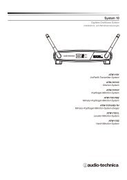
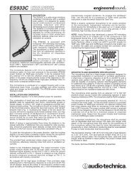
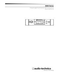
Front Panel Controls and Functions (Fig. B)<br />
1. POWER SWITCH: Press Power switch in and the receiver<br />
readouts will light.<br />
2. ALERT INDICATOR: The Alert Indicator lights:<br />
(a) When the receiver is in the Function Edit mode,<br />
(b) When no RF signal is received from transmitter,<br />
(c) When only one or two RF signal-strength bars are on,<br />
(d) When the transmitter is in the Mute mode,<br />
(e) When audio modulation level from the transmitter is<br />
close to the clipping point (AF +3/+6 bars),<br />
(f) When only one bar of the Battery “fuel gauge” is on<br />
(transmitter battery is weak).<br />
3. LCD WINDOW: Liquid Crystal Display indicates control settings and operational<br />
readings. See Figure D on page 2 for examples.<br />
4. TUNER OPERATION INDICATOR: Indicates which Tuner (A or B) has the better<br />
reception and is in operation. The “B” indicator also lights to serve as<br />
confirmation of Mode/Set button entries.<br />
5. UP/DOWN BUTTONS: Press Up or Down arrow buttons, in conjunction with the<br />
Mode/Set button, to step through menus, select operating frequency and edit<br />
receiver function choices.<br />
6. MODE/SET BUTTON: Use in conjunction with the Up/Down arrow buttons to step<br />
through menus, choose operating frequency, initiate automatic scanning and<br />
select receiver function options.<br />
7. MOUNTING ADAPTERS: For mounting the receiver in any standard 19" rack.<br />
Attach adapters to the receiver with the screws supplied and remove the four<br />
receiver feet. (Use optional AT8630 joining-plate kit to mount two ATW-R3100<br />
receivers side-by-side.)<br />
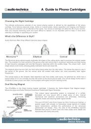
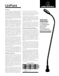
Rear Panel Controls and Functions (Fig. C)<br />
8. ANTENNA INPUT JACK: BNC-type antenna connector for Tuner “B.” Attach the<br />
antenna directly, or extend it with a low-loss antenna cable. See the “Antennas”<br />
section on page 5 for more details.<br />
9. ANTENNA INPUT JACK: Input for Tuner “A.” Attach the antenna directly, or<br />
extend it with a low-loss antenna cable.<br />
10. AF LEVEL CONTROL: Adjusts audio output level of both AF<br />
Output jacks; maximum output is fully clockwise.<br />
11. GROUND LIFT SWITCH: Disconnects the ground pin of the balanced output jack<br />
(12) from ground. Normally, the switch should be to the left (ground connected). If<br />
hum caused by a ground loop occurs, slide switch to the right (ground lifted).<br />
12. BALANCED AUDIO OUTPUT JACK: XLRM-type connector. A standard 2-conductor<br />
shielded cable can be used to connect the receiver output to a balanced micro<br />
phone-level input on a mixer or integrated amplifier.<br />
13. UNBALANCED AUDIO OUTPUT JACK: 1/4" phone jack. Can be connected to an<br />
unbalanced aux-level input of a mixer, guitar amp or tape recorder.<br />
14. POWER INPUT JACK: Connect the DC plug from the included in-line AC adapter.<br />
15. CORD HOOK: Loop the small DC cord around the cord hook to keep the DC plug<br />
from pulling out accidentally.<br />
Power On/Off<br />
To turn the receiver on, press in the Power switch. The Alert light and the LCD window<br />
will come on (about 1-2 seconds). The operating frequency will be displayed in the<br />
window after the power-up sequence. To turn the receiver off, press the Power switch<br />
again.<br />
LCD Window<br />
The LCD (Liquid Crystal Display) presents a great deal of setup and operating<br />
information clearly and conveniently. (See Figure D for examples.)<br />
Up/Down Arrow Buttons<br />
In conjunction with the Mode/Set button, the arrow buttons permit moving through the<br />
menu of functions, and choice of settings within each function.<br />
Mode/Set Button<br />
The Mode/Set button shifts the receiver from normal operation into Menu mode and, in<br />
conjunction with the Up/Down arrow buttons, permits selection of different features and<br />
changing of their stored values in the Edit mode.<br />
How to Make Setting Changes<br />
1. From the normal operating mode, press the Mode/Set button once to enter the<br />
Function Menu mode. (Only the frequency will remain in the LCD window, and the<br />
receiver’s audio output will be cut off.)<br />
2. Use the Up/Down arrow buttons to reach the desired function. The value in the<br />
LCD window is the current setting for that function.<br />
3. Press the Mode/Set button once again to open the list of available choices for that<br />
function. The value will flash, indicating that it can be changed (Edit mode).<br />
4. Use the arrow buttons to go through the available choices, stopping on the desired<br />
new choice.<br />
5. (a) To accept and enter the new choice, press and hold the Mode/Set button until<br />
“STORED” appears in the LCD. This changes the value and puts the function of the<br />
buttons back at Menu level (step 2 above). (The “B” tuner light will come on while<br />
the Mode/Set button is depressed, to confirm its action.)<br />
(b) To “back out” of the Edit mode without making a new choice, simply press the<br />
Mode/Set button once. The word “ESCAPE” will appear in the window and the<br />
function of the buttons will revert to the Menu level (step 2 above), without making<br />
any changes.<br />
6. Repeat this selection process for any other function changes desired. When<br />
finished with any changes, use the arrow buttons to move to “QUIT”. Press the<br />
Mode/Set button once to exit the menu and return the receiver to normal<br />
operation. (“RF” and “AF” will reappear in the window, indicating the return to<br />
normal receiver operation, with the receiver’s audio output again enabled.)<br />
E Band Frequency Scan Group Selection<br />
To select frequency Scan Group G1 Germany, G2 France or G3 Nordic (example page<br />
16). With the power off, Press and hold upper arrow key while powering on. Select the<br />
required Frequency Scan Group G1, G2 or G3 by pressing the "Mode/Set Button" until<br />
the desired group appears in the display.To store the selected frequency Scan Group,<br />
press the power switch to turn the receiver OFF, then press the power switch to turn the<br />
power on.<br />
When the receiver is in the Menu or Edit mode, its audio output is silenced. Once<br />
control-setting operations are completed (or Escape is used), normal receiver<br />
operation will resume with its audio output restored.<br />
While in the Edit mode, if no action is taken for approximately 30 seconds (no<br />
buttons pressed), the receiver will “back out” to the Menu mode. Similarly, after<br />
about 30 seconds of inaction in the Menu mode, the receiver will “back out” to<br />
normal receiver operation with audio output restored.<br />
How to Restore Default Settings<br />
To return all the receiver functions to their original factory-default settings, first turn the<br />
receiver off. Then hold in the Mode/Set button while pressing the Power switch. The<br />
LCD will briefly show “RESET”, followed by “WAIT” (release the Mode/Set button),<br />
before commencing normal-mode operation at the default settings.<br />
High-pass Filter<br />
Internal high-pass filter circuitry may be set to four positions: High-pass Off, or a 6 dB,<br />
12 dB or 18 dB slope at 150 Hz. The default setting is Off (“HP OFF”). Increasing the<br />
slope of the high-pass filter further suppresses unwanted low frequencies, while<br />
maintaining the frequency response in the desired audio range.<br />
6